
Hybrid fuzzy braking method for brushless direct-current motor of electric vehicle
A technology of brushed DC motor and hybrid braking, which is applied in the direction of stopping devices, etc., can solve the problems of unfavorable energy saving and environmental protection, and reduce energy use efficiency
Patent Information
- Authority / Receiving Office
- CN · China
- Current Assignee / Owner
- Publication Date
- 2013-04-03
- Estimated Expiration
- Not applicable · inactive patent
Smart Images
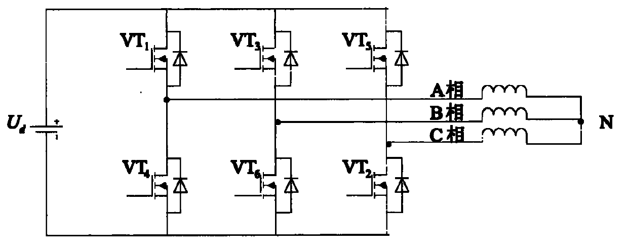
Figure 1 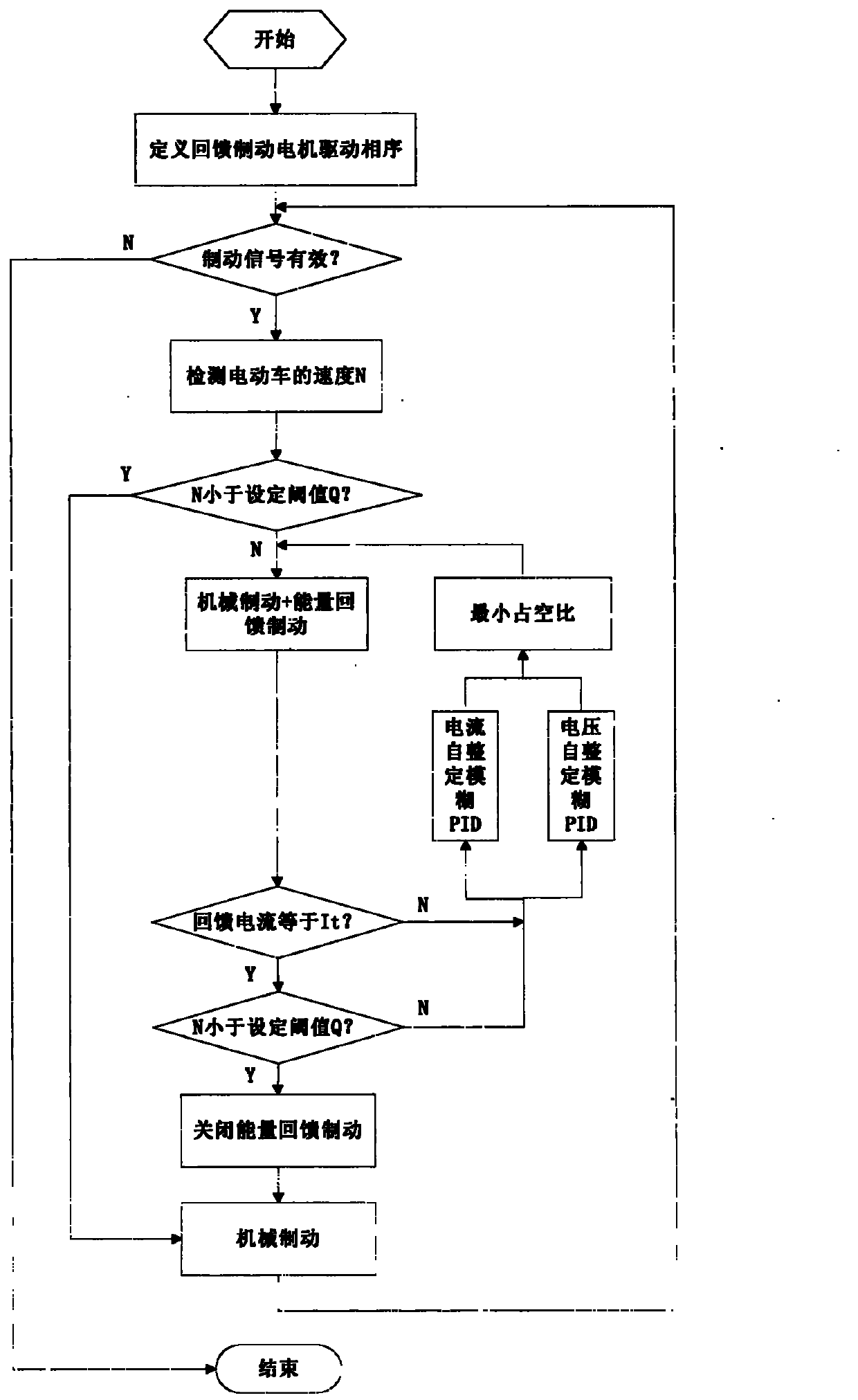
Figure 2
Abstract
Description
Technical field
[0001] The present invention relates to the field of electric vehicles, in particular to a brushless DC motor braking technology for electric vehicles. Background technique
[0002] As a new type of transportation, electric vehicles have a series of advantages such as green, environmental protection, energy saving, low noise, compactness, flexibility, and moderate price, and they have been widely used.
[0003] Electric vehicles are generally driven by brushless DC motors. There are usually mechanical brakes and electrical brakes to brake the brushless DC motors of electric vehicles. Among them, the electrical brakes are divided into reverse braking and energy feedback braking. Neither mechanical braking nor electrical reverse braking returns energy to the power source, which reduces the efficiency of energy use and is not conducive to energy saving and environmental protection. With the enhancement of energy conservation, emission reduction and environmental prot...
Examples
Embodiment Construction
[0015] In order to deepen the explanation of the present invention, the present invention will be described in further detail below in conjunction with the accompanying drawings. This embodiment is only used to explain the present invention and does not constitute a limitation on the protection scope of the present invention.
[0016] The braking method of a brushless DC motor for an electric vehicle according to the present invention has specific implementation steps as follows:
[0017] 1. Such as figure 1 As shown, VT1~VT6 are driving power tubes. The motor has 3 states in one cycle, and the phase changes every 120°. Therefore, only 3 steps are needed to define the phase sequence of driving the power tube when the energy is fed back to the brake motor: first step, Turn on VT4, turn off VT6, VT2; the second step, Turn on VT6, turn off VT4, VT2; the third step, Turn on VT2, turn off VT4, VT6; then according to the position signal of the Hall element, combined with the defined ph...