New method of intelligent repair monitoring equipment combining fault detection and workflow

A technology for fault detection and monitoring equipment, used in data processing applications, television, computing, etc., to solve complex and large problems in discovering and troubleshooting

Inactive Publication Date: 2013-04-03
PCI TECH GRP CO LTD
View PDF6 Cites 8 Cited by
  • Summary
  • Abstract
  • Description
  • Claims
  • Application Information

AI Technical Summary

Problems solved by technology

The work of discovering and eliminating these faults also becomes more and more complicated and huge with the expansion of the monitoring system
The previous method of relying on manual inspection and repair of dozens or hundreds of units has been impossible to meet the current requirements of efficient work

Method used


Image

  • New method of intelligent repair monitoring equipment combining fault detection and workflow
  • New method of intelligent repair monitoring equipment combining fault detection and workflow

Examples


Embodiment 1

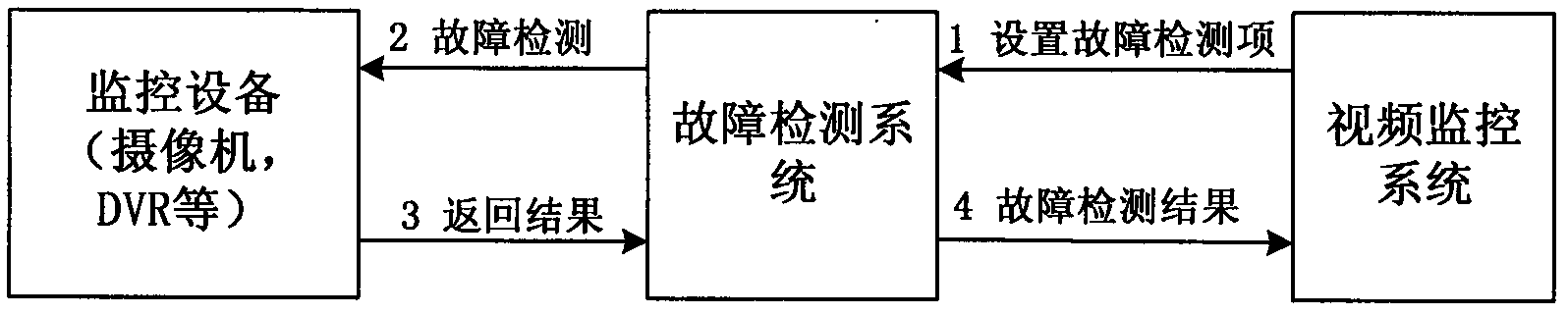
[0019] Embodiment 1, see FIG. 1 .

[0020] The invention provides a fault detection system and a workflow system, including the integration of the fault detection system and the workflow system by a video monitoring system;

[0021] Described fault detection system is used for: carrying out fault detection to video camera, monitoring equipment such as DVR, such as for video camera, can detect whether the video signal is interrupted, whether video is blocked, whether the state such as signal loss, then can detect whether hard disk is full for DVR , hard disk error;

[0022] The workflow system is used for: customizing the workflow, generating a work order according to the flow, and at the same time knowing the current processing status of a certain work order in real time, and deciding whether to automatically process the reminder according to the situation. The repair work orders generated by false positives can be cancelled.

[0023] By logging into the video surveillance s...

Embodiment 2

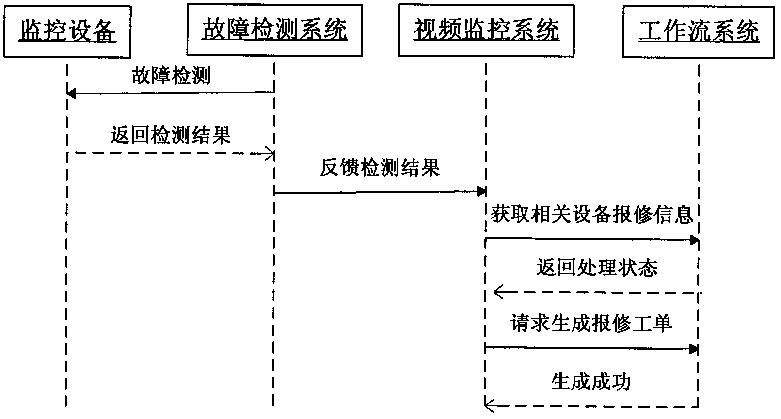
[0031] Example 2, see Fig. 2.

[0032] The present invention also provides a method for a video monitoring system to automatically generate a repair work order by using a workflow system, including:

[0033] According to the equipment repair requirements of the video surveillance system, the maintenance report workflow is customized. When the video surveillance system receives the detection results of the fault detection system, if it needs to generate a repair report work order, it only needs to notify the workflow system to generate a work order, and the work The flow system will generate corresponding repair work orders according to the requirements and enter the repair process flow. The workflow is shown in Figure 2, which specifically includes the following steps:

[0034] Step 1, the fault detection system detects the monitoring equipment;

[0035] Step 2, the fault detection system obtains the fault detection result;

[0036] Step 3, the fault detection system feeds b...


PUM


Abstract

The invention discloses a new method of intelligent repair monitoring equipment combining fault detection and workflow. The new method comprises a fault detecting system, a video monitoring system and a workflow system, wherein the fault detecting system is used for detecting faults of monitoring equipment such as a vidicon, and a digital video record (DVR), collecting fault information and feeding the fault information to a video monitoring platform; the video monitoring system is used for implementing unified management on the monitoring equipment such as the vidicon and the DVR, collecting and processing detection results of the fault detecting system simultaneously, and requiring the workflow system to automatically generate a repair worksheet according to circumstances; and the workflow system is used for automatically generating a repair worksheet in different circumstances and different ranks according to the types of the fault equipment, the generated fault types and the fault situations as well as the fault detection information collected by the video monitoring system combining with a pre-customized repair procedure, and entering repair procedure flow. Meanwhile, the video monitoring system can also acquire the latest processing situation of the repair worksheet of certain monitoring equipment in real time through the workflow system, so as to avoid repeated sheet filling.

Description

technical field [0001] The invention relates to the field of video monitoring and the field of workflow, in particular to a new method for intelligent repair monitoring equipment combined with fault detection and workflow. Background technique [0002] With the continuous development of current monitoring applications, the monitoring system is getting bigger and bigger, there are more and more connected devices, and the running time is getting longer and longer. Equipment failures are inevitable. The work of discovering and eliminating these faults also becomes more and more complex and huge with the expansion of the monitoring system. The previous method of relying on manual inspection and repair of dozens or hundreds of units has been impossible to meet the current requirements of efficient work. In order to meet the requirements of the current new situation and to give full play to the role of the monitoring system, it is necessary to introduce more advanced monitoring e...

Claims


Application Information

Patent Timeline
IPC IPC(8): H04N17/00G06Q10/06
Inventor 汪刚陈天玉李会永
Owner PCI TECH GRP CO LTD
Why Eureka
Try Eureka