
Fault detection method and device for starting loop of UHV flexible direct current transmission system

A technology of fault detection and start-up circuit, which is applied in the direction of fault location, information technology support system, fault detection according to conductor type, etc. It can solve the problems of limited manufacturing process level of connecting transformers and unsuitable outdoor layout of connecting transformers, etc.

Active Publication Date: 2019-08-02
ELECTRIC POWER RESEARCH INSTITUTE, CHINA SOUTHERN POWER GRID CO LTD
View PDF4 Cites 0 Cited by
  • Summary
  • Abstract
  • Description
  • Claims
  • Application Information

AI Technical Summary

Problems solved by technology

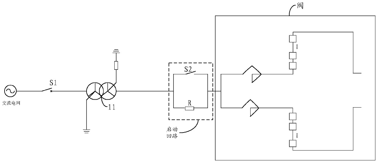
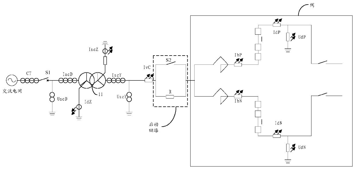
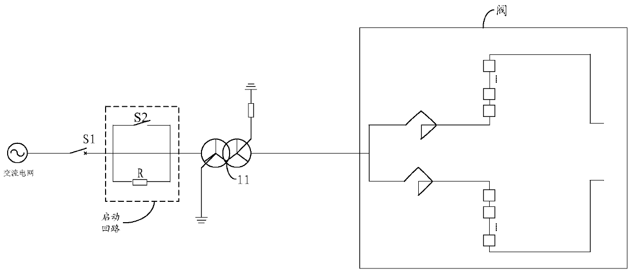
[0003] refer to figure 1 As shown, in the charging circuit in the current general flexible direct current transmission (voltage level ±350KV) system, the starting resistor R is set on the valve side of the connection transformer 11, and the part consisting of the starting resistor R and the switch S2 is called the starting circuit, because Considering the particularity of the power transmission grid, once a fault occurs, it will cause a big fault if it is not dealt with in time. figure 2 As shown in , it is necessary to figure 1 Add some current transformers and voltage transformers to some positions in the charging circuit shown in to measure the current or voltage in different places, and then judge whether there is a fault in the charging circuit according to each measurement result; Because of its high voltage level (voltage level ± 800KV), and the current level of production technology of the connection transformer is limited, the connection transformer of high voltage level is not suitable for outdoor layout, and the wall bushing is required. At this time, if the start-up circuit is to be set to connect the valve side of the transformer, it can only be set in the valve hall where the valve part is located, and because the start-up resistance itself is very large, it will greatly occupy the valve Part of the space, in order to ensure later maintenance, it is necessary to expand the valve hall so that the start-up circuit and valves can be installed in the valve hall, but this will cause a huge cost investment, so in order to reduce costs, the valve hall area needs to be reduced, refer to image 3 In the charging circuit of the UHV flexible DC transmission system shown, the starting resistor should be placed on the grid side of the connecting transformer, because the position of the starting circuit has changed, so it cannot be directly connected to the charging circuit. figure 2 The configuration concept of current or voltage transformers for fault detection in the starting circuit is applied as image 3 In the UHV flexible DC transmission system in China, for example, in the original configuration concept, electromagnetic current transformers are used to detect the current on the grid side to determine whether there is a fault for grid-side faults close to the AC system, but the grid-side generally uses Electromagnetic current transformer, while in image 3 During the charging process of the medium charging circuit, the current on the starting resistor network side is very small, only a few amps, and when a ground fault occurs on the starting resistor valve side, the current on the starting resistor network side is only tens of amps. If an electromagnetic current with a range of tens of amps is configured The transformer will have the problem of insufficient measurement accuracy under small current during normal operation. If an electromagnetic current transformer of several amps is configured, there will be a problem of dynamic stability of the transformer when a fault occurs. Excessive fault current will even cause mutual inductance. weapon explosion

Method used


Image

  • Fault detection method and device for starting loop of UHV flexible direct current transmission system
  • Fault detection method and device for starting loop of UHV flexible direct current transmission system
  • Fault detection method and device for starting loop of UHV flexible direct current transmission system

Examples


Embodiment Construction

[0034] The following will clearly and completely describe the technical solutions in the embodiments of the present invention with reference to the accompanying drawings in the embodiments of the present invention. Obviously, the described embodiments are only some, not all, embodiments of the present invention. Based on the embodiments of the present invention, all other embodiments obtained by persons of ordinary skill in the art without making creative efforts belong to the protection scope of the present invention.

[0035] It should be noted that, in the embodiments of the present invention, words such as "exemplary" or "for example" are used for example, illustration or illustration. Any embodiment or design solution described as "exemplary" or "for example" in the embodiments of the present invention shall not be construed as being more preferred or more advantageous than other embodiments or design solutions. Rather, the use of words such as "exemplary" or "such as" is...


PUM


Abstract

The invention provides a fault detection method and device for an UHV flexible DC transmission system start loop and can realize accurate fault detection on a start loop of a charging loop of an UHV flexible DC transmission system. The device comprises a first current measurement module used for measuring a first current value between an output end of an AC power grid and a first switch, a second current measurement module used for measuring a second current value between a start resistor and a first node, a third current measurement module used for measuring a third current value between a connection transformer and an input end of a valve, a voltage measurement module used for measuring a three-phase voltage value between a second node and a ground end, and a processing module used for connecting with the various modules to acquire the first current value, the second current value, the third current value and the three-phase voltage value, determining a fault type of a fault generated in the start loop according to the first current value, the second current value, the third current value and the three-phase voltage value, emitting the corresponding alarm information and simultaneously controlling the charging loop for stopping work.

Description

technical field [0001] The invention relates to the field of ultra-high voltage flexible direct current transmission, in particular to a fault detection method and device for a start-up circuit of an ultra-high voltage flexible direct current transmission system. Background technique [0002] At present, compared with conventional DC transmission technology, flexible DC transmission technology can achieve independent control of active power and reactive power, and does not require grid commutation voltage support, and can supply power to passive systems. It uses fully-controlled devices, instantaneous voltage The problem of commutation failure will not occur in the transient process such as drop, which has obvious technical advantages. Among them, UHV flexible direct current (referred to as UHV flexible direct current) transmission technology can transmit power over long distances and with large capacity, improve the problem of multi-DC feed-in at the receiving end, and impr...

Claims


Application Information

Patent Timeline
Patent Type & Authority Patents(China)
IPC IPC(8): G01R31/08
CPCG01R31/086Y04S10/52
Inventor 郭铸李明李岩许树楷刘涛曹润彬黄伟煌陈怡静李婧靓李春华
Owner ELECTRIC POWER RESEARCH INSTITUTE, CHINA SOUTHERN POWER GRID CO LTD
Learn More