
LED (light-emitting-diode) driving method and device

A technology of LED driving and ambient temperature, which is applied to lighting devices, lamp circuit layout, light sources, etc., and can solve problems such as the inability to adjust LED luminous power

Active Publication Date: 2013-04-03
深圳市飞锐照明有限公司
View PDF2 Cites 1 Cited by
  • Summary
  • Abstract
  • Description
  • Claims
  • Application Information

AI Technical Summary

Problems solved by technology

[0003] The purpose of the present invention is to provide a LED driving method, aiming to solve the problem that the existing LED driving method cannot adjust the LED luminous power according to the change of the ambient temperature

Method used


Image

  • LED (light-emitting-diode) driving method and device
  • LED (light-emitting-diode) driving method and device

Examples


Embodiment 1

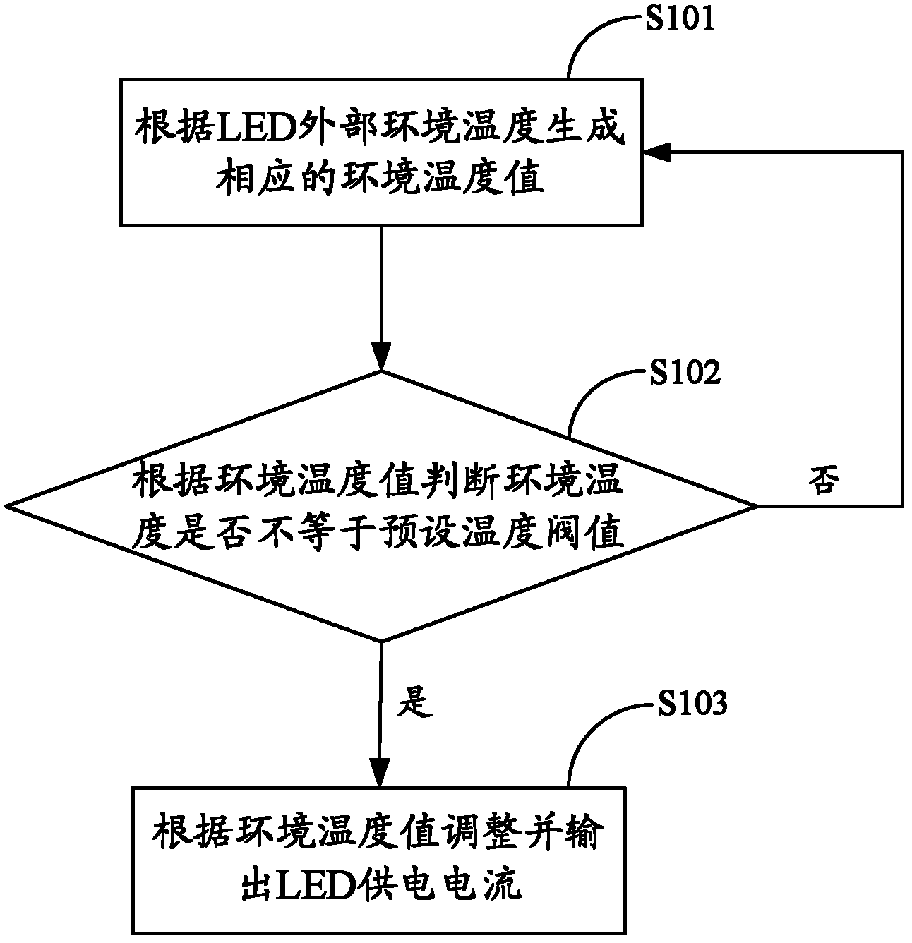
[0027] figure 1 The implementation process of the LED driving method provided by the first embodiment of the present invention is shown. For the convenience of description, only the parts related to the first embodiment of the present invention are shown, and the details are as follows:

[0028] In step S101, a corresponding ambient temperature value is generated according to the external ambient temperature of the LED.

[0029] In the embodiment of the present invention, step S101 is specifically:

[0030] Generate a corresponding ambient temperature analog signal at a specific time interval according to the external ambient temperature of the LED;

[0031] Convert the ambient temperature analog signal to the ambient temperature digital signal;

[0032] Convert the ambient temperature digital signal to the corresponding ambient temperature value.

[0033] Wherein, the specific time interval may be 2 seconds.

[0034] Among them, the conversion of the ambient temperature d...

Embodiment 2

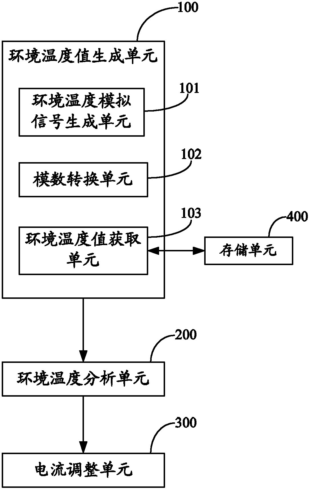
[0044] figure 2 The module structure of the LED driving device provided by the second embodiment of the present invention is shown. For the convenience of description, only the parts related to the second embodiment of the present invention are shown, and the details are as follows:

[0045] The LED driving device includes an ambient temperature value generation unit 100 , an ambient temperature analysis unit 200 , a current adjustment unit 300 and a storage unit 400 .

[0046] The ambient temperature value generation unit 100 is used to generate a corresponding ambient temperature value according to the external ambient temperature of the LED.

[0047] In the embodiment of the present invention, the ambient temperature value generation unit 100 is specifically:

[0048] An ambient temperature analog signal generating unit 101, configured to generate a corresponding ambient temperature analog signal according to the external ambient temperature of the LED at a specific time ...


PUM


Abstract

The invention belongs to the field of driving an LED (Light-Emitting Diode), and provides an LED driving method and device. The method comprises the steps of: generating an ambient temperature value corresponding to the ambient temperature, judging whether the ambient temperature is unequal to a preset temperature threshold value according to the ambient temperature value, and regulating an LED power supply current if the ambient temperature is unequal to the preset temperature threshold value, so that the luminescence power of the LED is controlled, the purpose of controlling the luminescence power of the LED according to the ambient temperature is achieved, the self temperature of the LED in working can keep constant, and the problem that the luminescence power of the LED can not be regulated according to the change of the ambient temperature by the conventional LED driving mode.

Description

technical field [0001] The invention belongs to the field of LED driving, in particular to an LED driving method and device. Background technique [0002] At present, as a new type of light source, LED is widely used in lighting and graphic display and other fields. The existing LED driving method is to use constant current direct drive, and if the ambient temperature changes greatly, the LED needs to adjust its own power according to the change of the ambient temperature, so that the temperature of the LED itself can be kept constant during operation to ensure It is in normal working order. However, the existing LED constant current driving method obviously cannot meet the above requirements. Therefore, the existing LED driving method has the problem of being unable to adjust the luminous power of the LED according to the change of the ambient temperature. Contents of the invention [0003] The purpose of the present invention is to provide an LED driving method, aimin...

Claims


Application Information

Patent Timeline
IPC IPC(8): H05B37/02
Inventor 杨东升
Owner 深圳市飞锐照明有限公司
Learn More