Winding tooth and component for an electrical machine for reducing eddy currents

A winding and component technology, applied in the field of winding teeth, can solve the problems of reducing motor efficiency and loss

Active Publication Date: 2013-04-03
ROBERT BOSCH GMBH
View PDF7 Cites 6 Cited by
  • Summary
  • Abstract
  • Description
  • Claims
  • Application Information

AI Technical Summary

Problems solved by technology

In general, eddy currents cause losses, thus reducing the efficiency of the motor and can cause localized heating of the tooth tips in the end sections of the assembly teeth in the stacking direction

Method used


Image

  • Winding tooth and component for an electrical machine for reducing eddy currents
  • Winding tooth and component for an electrical machine for reducing eddy currents
  • Winding tooth and component for an electrical machine for reducing eddy currents

Examples


Embodiment Construction

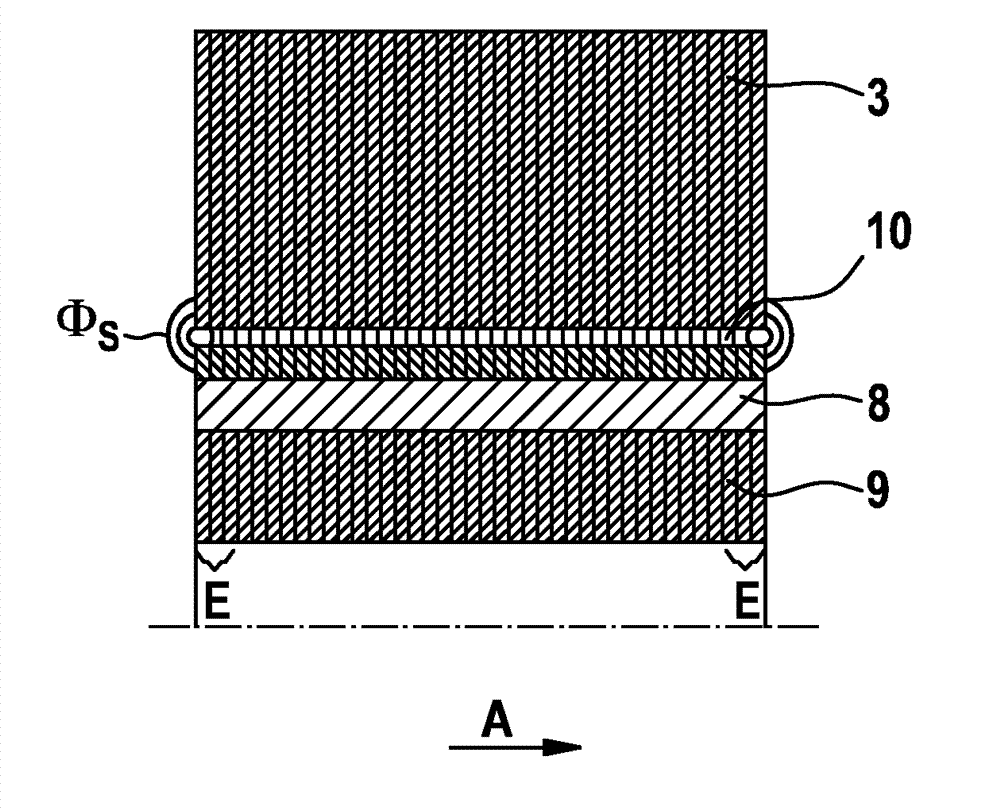
[0040] figure 1 A schematic cross-sectional view of a three-phase brushless permanent excitation motor with internal rotating parts, for example represented by motor 1 , is shown. The electric machine 1 comprises a cylindrical stator 2 with inwardly directed stator teeth 3 . In the present exemplary embodiment, the stator 2 comprises twelve stator teeth 3 which are each wound with a stator coil 4 as a winding coil. The stator coils 4 are connected to one another according to known wiring diagrams for three-phase motors.

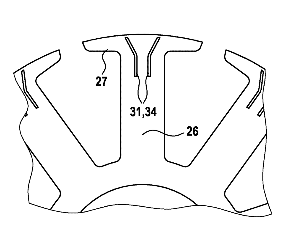
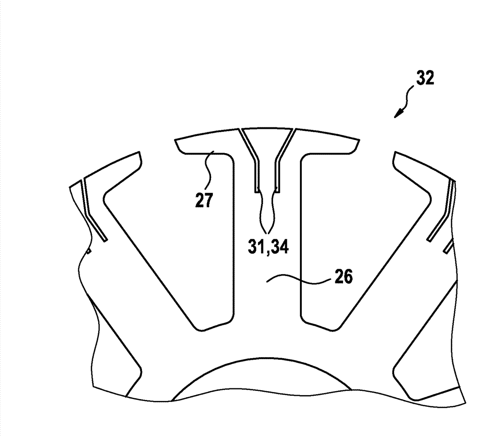
[0041] A tooth tip 5 is provided on the inwardly directed end of the stator tooth 3 , which correspondingly has an outer contour opposite the tooth shank. The outer contour of the tooth tips 5 forms an inner recess 6 which is substantially concentric with the cylindrical stator 2 .

[0042] The rotor 7 is arranged in the interior space as a rotating part of the electric machine 1 . In this exemplary embodiment the rotor 7 has permanent magnets 8 which are...


PUM


Abstract

The invention relates to a winding tooth (3) for a component (2) of an electrical machine (1), in particular for a stator and/or a rotor, comprising: a tooth shaft for being wound with a winding coil (4); and a tooth head (5) which is arranged at one end of the tooth shaft with respect to a winding axis; wherein one or more slots (14) are provided at at least one end section of the winding tooth (3), said slots extending along the winding axis through the tooth head (5), wherein the end section corresponds to a region at one or both ends of the winding tooth (3) along a transverse direction which runs substantially perpendicular to the winding axis.

Description

technical field [0001] The invention relates to a winding tooth for an assembly of an electric machine, in particular a winding tooth made of laminations. Background technique [0002] Typically an electric motor has a stator and a rotor that moves relative to the stator. Both the stator and the rotor can have teeth wound with winding coils into which an alternating current is fed during operation of the electric machine in order to generate a changing magnetic field. The magnetic field generated in this way is distributed through the stator teeth or rotor teeth towards the rotor or stator, wherein the distribution of the field lines of the magnetic field and thus the manner in which the magnetic field changes is determined by the shape of the outer contour of the tooth crests located on the teeth. The current optimization with regard to efficiency and operating characteristics merely adjusts the outer contour in the direction of the relative movement between rotor and stat...

Claims


Application Information

Patent Timeline
Patent Type & Authority Applications(China)
IPC IPC(8): H02K1/16H02K1/26H02K23/42
CPCH02K1/08H02K3/42H02K1/24H02K1/146
Inventor S.A.埃文斯
Owner ROBERT BOSCH GMBH
Why Eureka
Try Eureka