Rotor for electrical machine, in particular for a synchronous motor

A motor and rotor technology, applied in the field of rotor structure, can solve problems such as complex and heavy structures, and achieve the effect of low manufacturing cost and excellent smooth operation

Inactive Publication Date: 2013-04-03
BRUSA ELECTRONICS AG
View PDF6 Cites 7 Cited by
  • Summary
  • Abstract
  • Description
  • Claims
  • Application Information

AI Technical Summary

Problems solved by technology

However, due to the use of an additional metal tubular tank, this rotor has a more complex and heavier structure related to high manufacturing technical requirements

Method used


Image

  • Rotor for electrical machine, in particular for a synchronous motor
  • Rotor for electrical machine, in particular for a synchronous motor
  • Rotor for electrical machine, in particular for a synchronous motor

Examples


Embodiment Construction

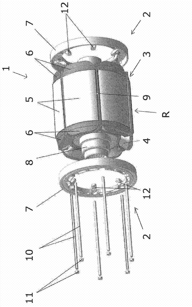
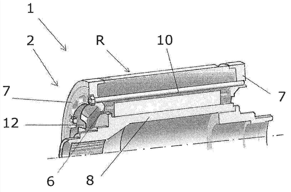
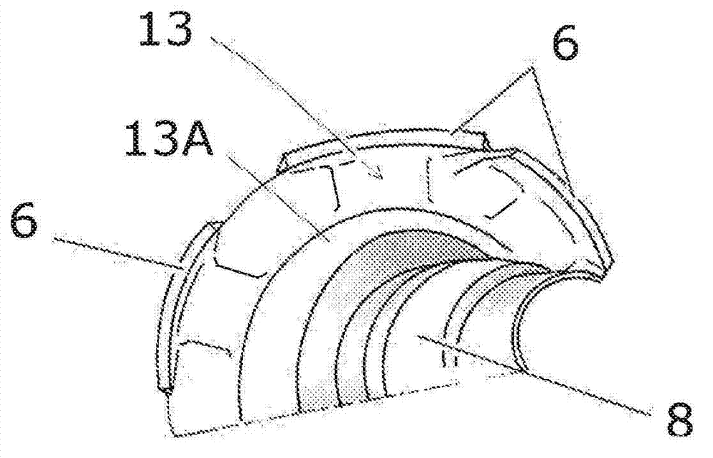
[0031] figure 1 A rotor assembly 1 according to the invention is shown comprising a rotor R shown in an exploded view and an exemplary embodiment of the proposed restraint system 2 . The restraint system 2 according to the invention comprises inner end caps 6 at both ends and a corresponding outer support ring 7 and is generally arranged as a protection device in order to fully restrain the winding ends 4 projecting from the laminations 3 in the axial direction. It is supported on both front sides of the rotor R and on the winding regions that may occur between the pole shoes 5 of the rotor R, even at relatively high rotational speeds of the rotor R. existfigure 1 In , the axis of the rotor R is denoted by reference numeral 8 .

[0032] The rotor assembly 1 provided with the restraint system 2 according to the invention is especially suitable for the rotor R of a current-excited synchronous motor (SSM) or other electric motors having windings on the rotor, which are used in p...


PUM


Abstract

The present invention relates to a rotor (R) of an electrical machine, in particular a synchronous motor of electric vehicle drives, which rotor (R) comprises a rotor shaft (8), a sheet stack (3), windings, and a restraining system (2) with support elements. The support elements of the restraining system include support rings (7) which protect winding heads (4) projecting from the sheet stack (3) in the axial direction against, preferably radial, stresses. In the invention the elements of the restraining system (2) protecting the winding heads (4) from stresses also include axially inner end caps (6) which are configured on the one hand as support means for the finished winding heads (4) in the operating state and on the other hand as guide and support means during the winding of the pole windings of the rotor (R) about the axial edge of the sheet stack (3). The axially outer support rings (7) cooperate with the axially inner end caps (6) in such a manner that the support rings (7) can absorb the centrifugal forces acting on the end caps (6) of the winding heads (4).

Description

[0001] This application claims priority to, and as a non-provisional application of, earlier U.S. Provisional Application No. 61 / 364,439, filed July 15, 2010; this application also claims the earlier European Application, filed July 14, 2010 Priority of No. EP10169565; European Application No. EP10169565 and U.S. Application No. 61 / 364,439 are hereby expressly incorporated by reference in their entirety for all content and purposes, as if both were hereby as clearly stated. technical field [0002] The invention relates to a rotor structure for an electric motor, in particular a synchronous motor of an electric vehicle drive, wherein the rotor comprises a rotor shaft, laminations, windings and a restraint system with support elements. Background technique [0003] When the rotor of a synchronous motor rotates at high rotational speeds, high radial forces develop in the rotor coils which try to bend the coil ends or winding ends radially outwards. The main task of the restra...

Claims


Application Information

Patent Timeline
Patent Type & Authority Applications(China)
IPC IPC(8): H02K3/52H02K15/16
CPCH02K7/04H02K3/38H02K1/325H02K3/51H02K3/527Y02T10/641H02K15/165H02K9/06Y02T10/64H02K3/52H02K15/16H02K1/22
Inventor A·霍泽内尔
Owner BRUSA ELECTRONICS AG
Why Eureka
Try Eureka