Splitting type rotor for powder concentrator and manufacturing process of splitting type rotor

A split-type, powder separator technology, which is used in the separation of solids from solids by air flow, solids separation, chemical instruments and methods, etc., to achieve the effects of convenient storage, reduced operating costs, and improved production efficiency and economic benefits.

Inactive Publication Date: 2013-04-10
LV TECH ENG TIANJIN CO LTD
View PDF7 Cites 6 Cited by
  • Summary
  • Abstract
  • Description
  • Claims
  • Application Information

AI Technical Summary

Problems solved by technology

[0005] The main purpose of the present invention is to address the above problems, to provide a split rotor for a powder separator and its manufacturing process, to facilitate storage, transportation, and reduce operating costs to ensure t

Method used


Image

  • Splitting type rotor for powder concentrator and manufacturing process of splitting type rotor
  • Splitting type rotor for powder concentrator and manufacturing process of splitting type rotor
  • Splitting type rotor for powder concentrator and manufacturing process of splitting type rotor

Examples


Embodiment 1

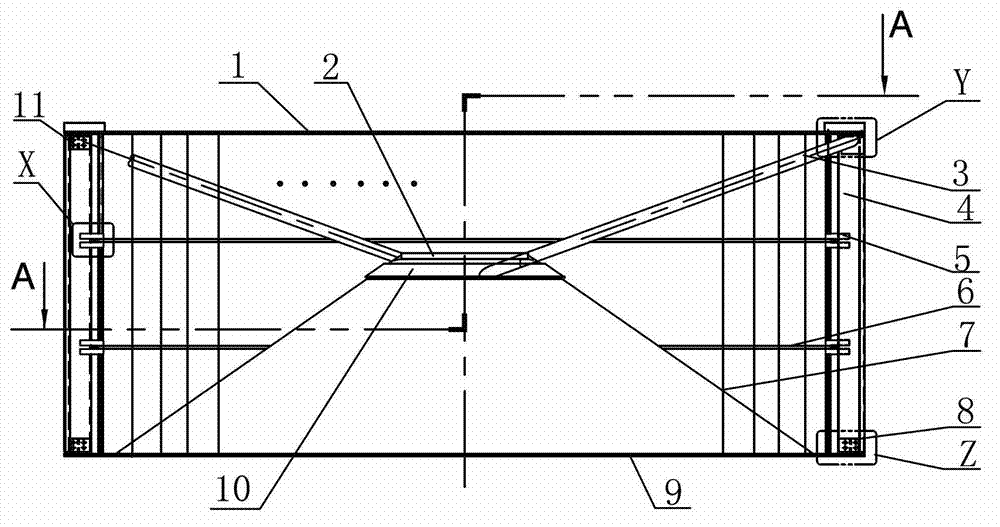
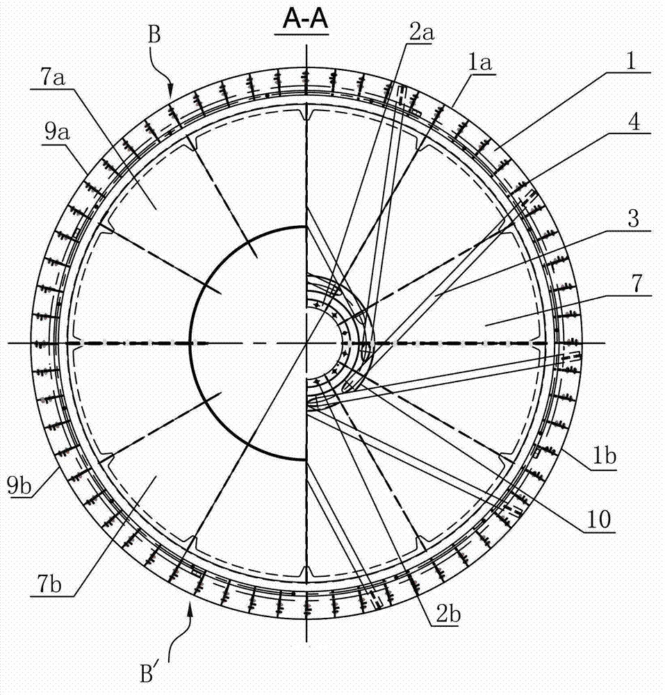
[0036] Figure 1 to Figure 10 A split rotor for a powder separator is shown, including a cage rotor body formed by coaxial circular upper and lower flanges 1, 9 and blades 4 uniformly distributed and fixed between the upper and lower flanges parallel to the above-mentioned axis and The rotor body is coaxially arranged inside the rotor cone 7, and the rotor cone 7 is a conical cylinder whose bottom edge is fixedly connected to the above-mentioned lower flange 1 and the top edge is connected to the cone flange 2. It is characterized in that the above-mentioned split rotor is It is composed of two semi-circular rotors B and B' that are separated by the plane of the axis butt joint. The above-mentioned semi-circular rotors B and B' respectively include a semi-circular cage-type rotor body formed by semi-circular upper and lower flanges and blades, a semi-circular rotor cone and a The semicircular rotor cone connected semicircular flange, that is, the semicircular rotor B includes ...

Embodiment 2

[0043] The present invention also provides a manufacturing process of the above-mentioned split rotor for the powder classifier, and specifically elaborates the following steps embodying the characteristics of the process in conjunction with Example 1:

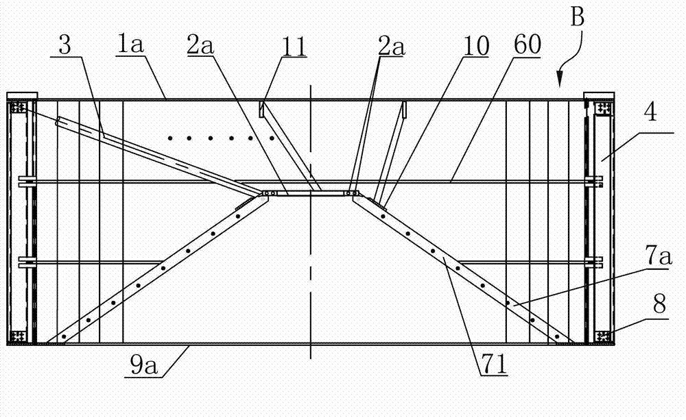
[0044] ⑴Material preparation, according to product design requirements, prefabricated the upper and lower flange splicing sections with even segments respectively, the rotor cone 7 with ring cone reinforcement slat 10 composed of two semicircular rotor cones 7a, 7b movably connected, composed of two The conical flange 7, the upper and lower connecting plates 11, 8 and the blade 4 formed by the movable connection of the semi-conical flanges 7a and 7b, according to embodiment 1, two semi-circular upper flanges 1a, 1b, lower flange 9a, When 9b is used in combination, the joints are connected by welding, the semicircular rotor cones 7a, 7b are connected by bolts through the connecting edge 71 arranged along the joints, and the semi...


PUM

PropertyMeasurementUnit
Diameteraaaaaaaaaa

Abstract

The invention relates to a splitting type rotor for a powder concentrator and a manufacturing process thereof. The rotor comprises a cage type rotor body formed by upper and lower flanges and blades, and a rotor cone which is coaxial with the rotor body and is arranged inside the rotor body. The rotor is characterized in that the splitting type rotor is formed by abutting two semicircular rotors which are divided through an axis plane. The manufacturing process comprises the following steps of: (1) preparing materials; (2) establishing a horizontal worktable; (3) drawing outer edge lines of the upper and lower flanges on the worktable and marking a circle center; (4) splicing the upper and lower flanges; (5) mounting the rotor cone; (6) mounting a cone flange; (7) mounting the upper flange and the blades, and weighing and encoding the blades; mounting according to an encoding sequence; in all the steps, adjusting the roundness, the coaxiality and the levelness and controlling the dimensional tolerance; (8) adjusting the balance of an integrally-grouped rotor; and (9) detaching the balanced rotor into two semicircular rotors and packaging and strengthening. The splitting type rotor disclosed by the invention has the advantages of convenience for storage and transportation and reduction of operation cost; the rotor blades can be replaced online and the production efficiency and the economic benefit are improved.

Description

technical field [0001] The invention relates to a structural part of a powder separator and a manufacturing process thereof, in particular to a split rotor for a powder separator and a manufacturing process thereof. Background technique [0002] In industries involving material crushing and grinding, such as building materials, electric power, and coal processing, material powder selection equipment is an indispensable key equipment. Taking cement production in the building materials industry as an example, the particle size of materials after grinding must meet the requirements of calcination. Therefore, a classifier is required for classification, and the new compound particles generated after calcination also need to be pulverized and classified by a classifier to form products; in addition, coal used as fuel in many industries such as cement and electric power also requires pulverization. Grinding and grading. This shows the importance and large number of powder separat...

Claims


Application Information

Patent Timeline
IPC IPC(8): B07B7/083
Inventor 贺明华张俊廷
Owner LV TECH ENG TIANJIN CO LTD
Why Eureka
Try Eureka