Method for online treatment of water leakage of cooling wall water supply branch pipe of blast furnace hearth

A technology for water supply branch pipes and blast furnaces, which is applied in the direction of cooling devices, etc., can solve the problems of reducing the temperature of refractory materials, affecting the longevity of blast furnaces, and uneconomical problems, achieving the effects of reducing losses, improving safety and reliability, and high work efficiency

Inactive Publication Date: 2016-02-24
NANJING IRON & STEEL CO LTD
View PDF5 Cites 4 Cited by
  • Summary
  • Abstract
  • Description
  • Claims
  • Application Information

AI Technical Summary

Problems solved by technology

[0002] The characteristic of the blast furnace smelting process is that a variety of intricate physical and chemical changes are completed during the countercurrent movement of the charge and gas, during which high-temperature gas and slag iron up to 1500 degrees Celsius are produced, which affects the life of the blast furnace shell and refractory materials. Therefore, a cooling wall is set between the blast furnace shell and the refractory material, and the heat is taken away through the cooling wall to reduce the temperature of the refractory material, thereby prolonging the service life of the refractory material. The existing cooling system cools from bottom to top, and the entire cooling cycle The pressure of the system is relatively high, at 0.6-1Mpa. The current method to deal with the leakage of the water supply branch pipe of the cooling wall of the blast furnace hearth is: after the wind is shut down for 15 days, the temperature in the blast furnace is lowered, and the cooling water of the furnace shutdown is replaced. The method has a long construction period and is not expensive. Economical, affecting the longevity of the blast furnace, high cost, unable to meet existing needs

Method used


Image

  • Method for online treatment of water leakage of cooling wall water supply branch pipe of blast furnace hearth

Examples


Embodiment 1

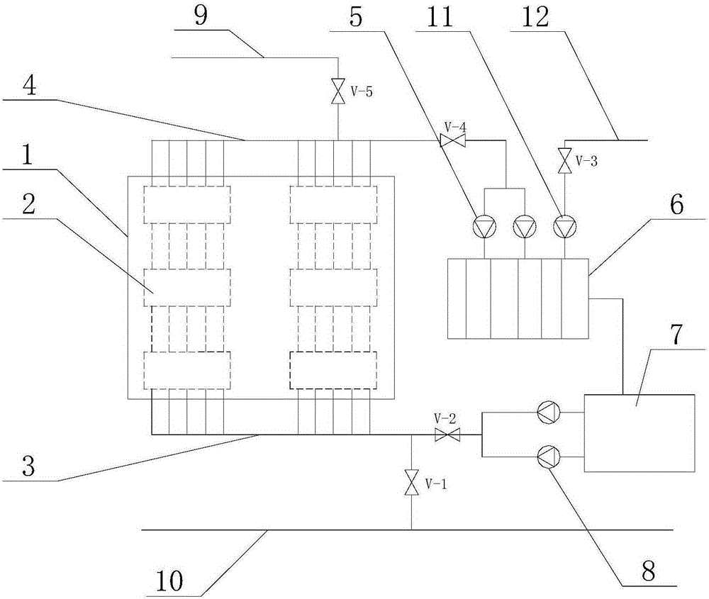
[0019] This embodiment provides a method for on-line treatment of water leakage from a water supply branch pipe of a blast furnace hearth cooling stave. The cooling stave of a blast furnace hearth 1 treated by this method is provided with a plurality of cooling cavities 2. The cooling cavities 2 in the height direction pass through vertical pipes. The straight branch pipes are connected, the lower end of the blast furnace hearth 1 is provided with a hearth water supply pipe 3, the upper end of the blast furnace hearth 1 is provided with a hearth water outlet pipe 4, and the hearth water outlet pipe 4 is connected with the cooling tower 6 through the first water pump 5, and the cooling tower 6 is connected to the reservoir 7, the reservoir 7 is communicated with the hearth water supply pipe 3 through the second water pump 8, a valve V-4 is provided between the first water pump 5 and the hearth water outlet pipe 4, and the second water pump 8 is connected to the hearth water suppl...


PUM


Abstract

The invention discloses a method for online treatment of water leakage of a cooling wall water supply branch pipe of a blast furnace hearth. The method comprises the following steps that when the cooling wall water supply branch pipe or valves of the blast furnace hearth leak water, the valve V-2 and the valve V-4 are closed firstly, then the valve V-1 and the valve V-5 are opened, the pressure of a water inlet pipe is controlled to be within 0-0.1 Mpa, and therefore a whole cooling system can conduct cooling from top to bottom; when detection data meet following requirements, maintaining and replacing begin to be conducted, wherein the specific requirements include that the water temperature in a furnace hearth water supply pipe is smaller than 45 DEG C, the temperature difference of water in the water inlet pipe and water in the furnace hearth water supply pipe is smaller than 2 DEG C, and the temperature of the side wall of the blast furnace heart is smaller than 200 DEG C; and when maintaining is completed, the valve V-1 and the valve V-5 are closed, the valve V-2 and the valve V-4 are opened, the valve V-3 is opened, and supplemental water is added into a cooling circulation system through a third water pump.

Description

technical field [0001] The invention relates to a blast furnace hearth cooling circulation system, in particular to a method for on-line treatment of water leakage in a water supply branch pipe of a blast furnace hearth cooling wall. Background technique [0002] The characteristic of the blast furnace smelting process is that a variety of intricate physical and chemical changes are completed during the countercurrent movement of the charge and gas, during which high-temperature gas and slag iron up to 1500 degrees Celsius are produced, which affects the life of the blast furnace shell and refractory materials. Therefore, a cooling wall is set between the blast furnace shell and the refractory material, and the heat is taken away through the cooling wall to reduce the temperature of the refractory material, thereby prolonging the service life of the refractory material. The existing cooling system cools from bottom to top, and the entire cooling cycle The pressure of the sys...

Claims


Application Information

Patent Timeline
Patent Type & Authority Applications(China)
IPC IPC(8): C21B7/10
Inventor 何英吴泽勇熊飞武张明星
Owner NANJING IRON & STEEL CO LTD
Why Eureka
Try Eureka