Multi-cylinder rotary type compressor

A rotary compressor and multi-cylinder technology, which is applied to rotary piston/swing piston pump components, elastic fluid rotary piston/swing piston pump combinations, mechanical equipment, etc., can solve the lack of shaft rigidity , the reduction of piston efficiency, the increase of the compression load of the compression chamber, etc., to achieve the effect of improving wear failure and compression efficiency reduction, improving rigidity and vibration

Active Publication Date: 2013-04-10
GUANGDONG MEIZHI COMPRESSOR
View PDF12 Cites 14 Cited by
  • Summary
  • Abstract
  • Description
  • Claims
  • Application Information

AI Technical Summary

Problems solved by technology

[0003] In a large-capacity rotary compressor composed of multiple cylinders, not only the compression load on the compression chamber increases, but also the shaft length from the main bearing to the sub-bearing becomes longer, so there is a problem that the shaft rigidity of this part is insufficient
As a result, reduced efficiency due to eccentric shaft wear and incorrect action of the piston

Method used


Image

  • Multi-cylinder rotary type compressor
  • Multi-cylinder rotary type compressor
  • Multi-cylinder rotary type compressor

Examples


Embodiment 1

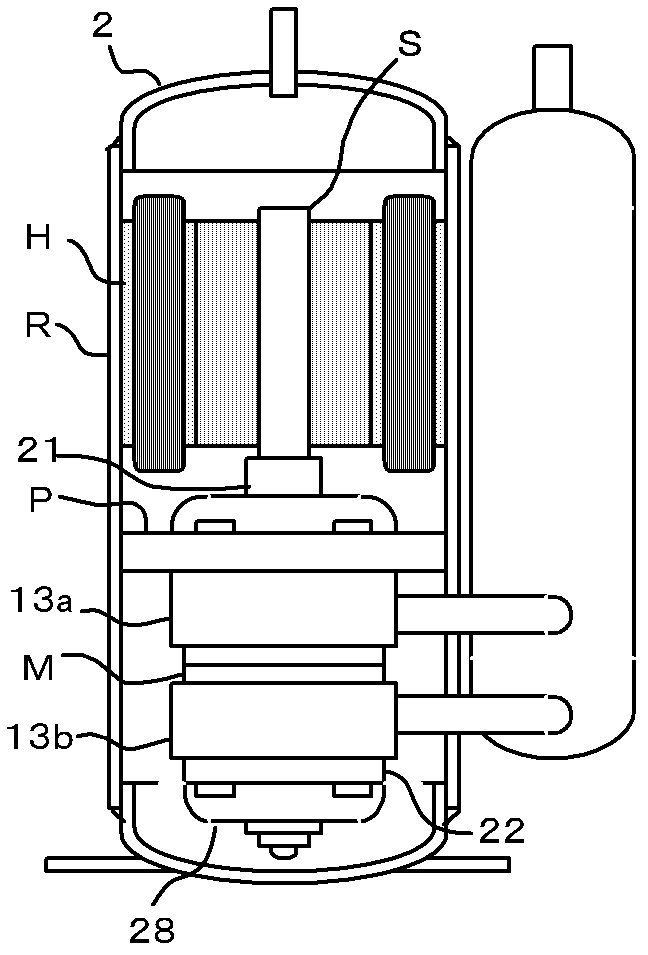
[0039] see figure 1 , is the internal structure of the rotary compressor R. The rotary compressor R is equipped with a compression mechanism P and a motor H in a sealed casing, which are fixed at the inner wall of the casing. The first cylinder 13a and the second cylinder 13b of the compression mechanism P are partitioned by a partition M.

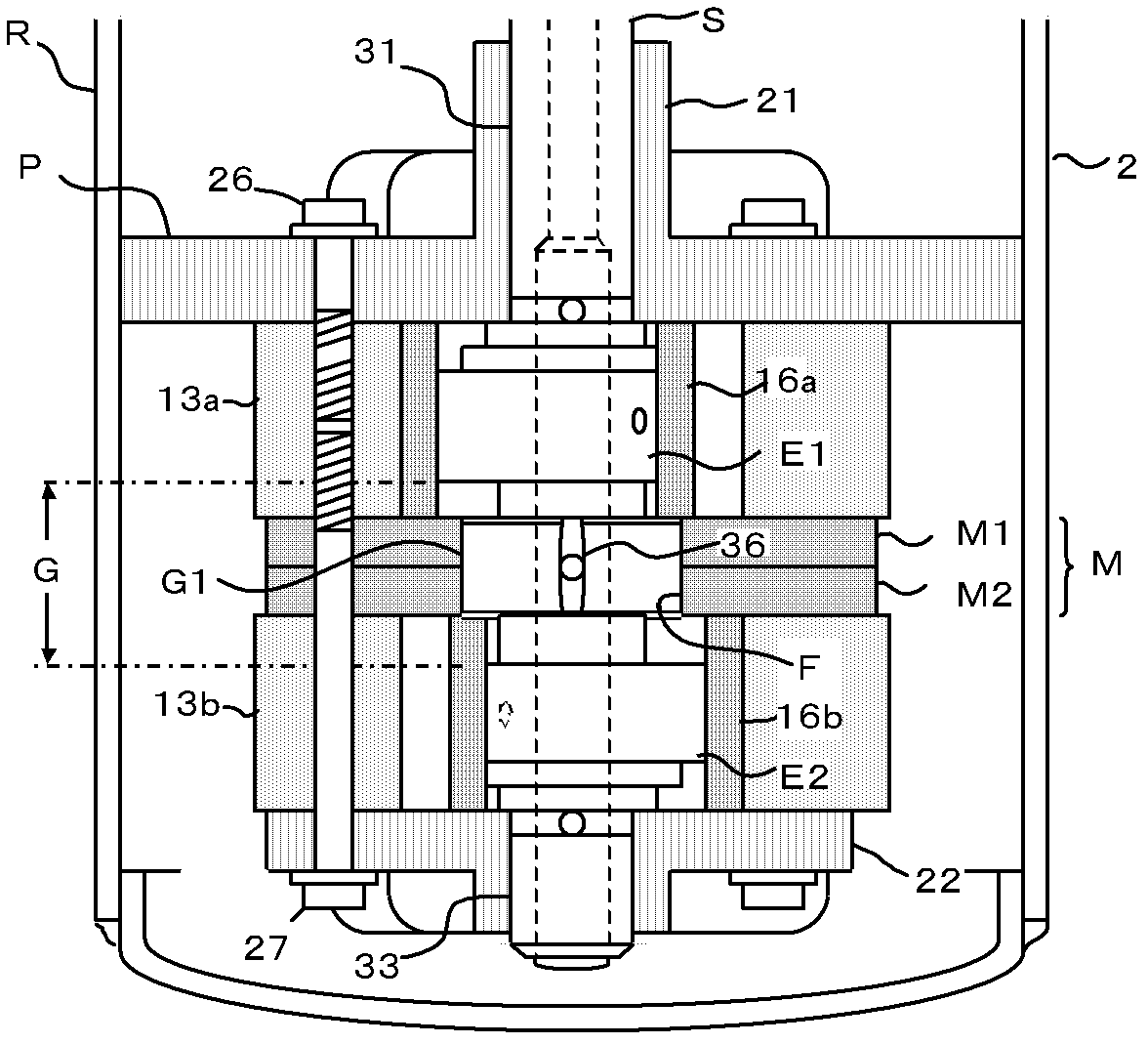
[0040] see figure 2 , is a detailed view of the compression mechanism P. In the first cylinder 13a and the second cylinder 13b constituting the compression mechanism P, a first piston 16a and a second piston 16b are arranged, and slide plates (not shown) that reciprocate in synchronization with them are arranged. A central partition M consisting of a first plate M1 and a second plate M2 divides the two cylinders between these cylinders.

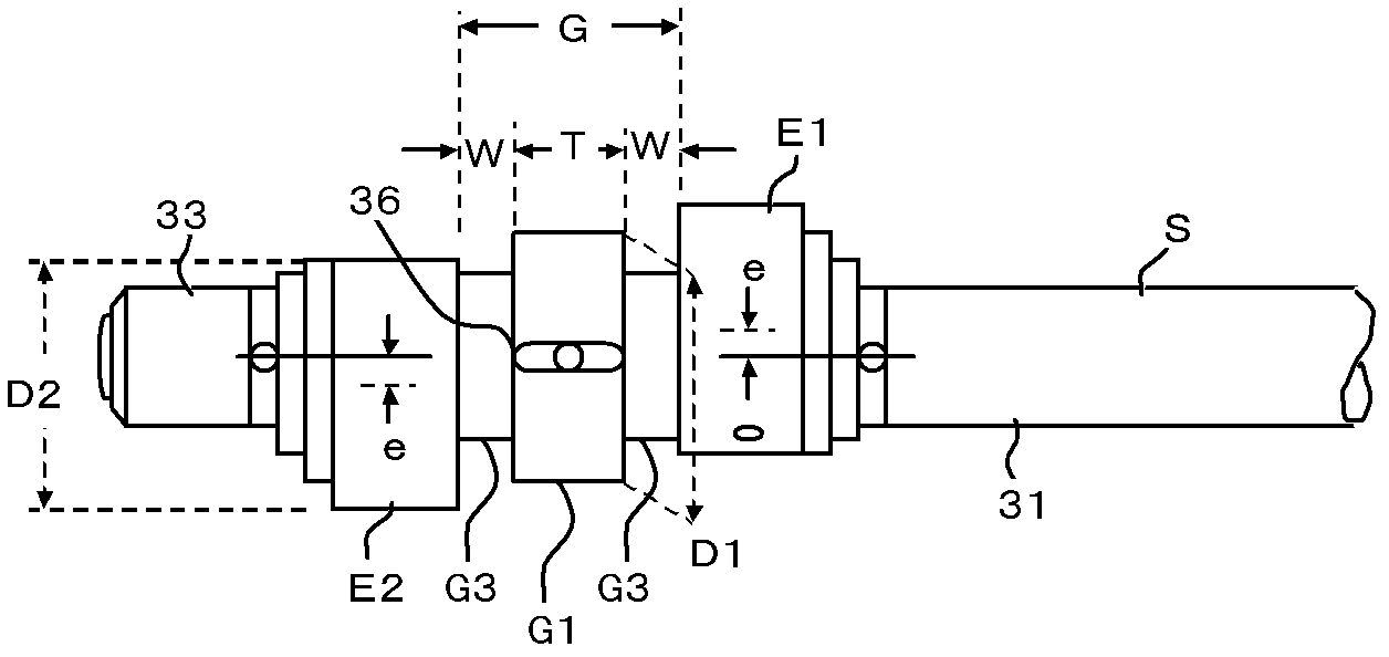
[0041] The connecting shaft G of the eccentric crankshaft S arranged at the center of the compression mechanism P is a shaft connecting the first eccentric shaft E1 and the second eccentric shaft E2,...

Embodiment 2

[0053] see Figure 9-Figure 10 , in this embodiment 2, a central groove 45 with an inner diameter of d2 is disposed in the center of the second plate M2, and a central hole 44 with an inner diameter of d1 is opened on the outer plane of the central groove 45 .

[0054] In Embodiment 2, the inner diameter d3 of the central groove 45 is the inner diameter of the intermediate bearing F, so d2=d3. d2=d1+2e, a thin-walled thrust portion 46 is formed at the bottom of the central groove 45, see Figure 10 . As in Embodiment 1, d2=d3=D1+c. Also, d1=D2+c.

[0055] see Figure 11 , represents the process of inserting the second plate M2 into the eccentric crankshaft S and assembling the middle partition M. Same as Embodiment 1, when the second flat plate M2 moves upward through the outer periphery of the second eccentric shaft E2, as Figure 11 . Moreover, in order to ensure that the center of the center hole 44 coincides with the center of the main shaft 31, it needs to be moved...

Embodiment 3

[0061] see Figure 13 , the present embodiment 3 is that one flat plate constitutes the intermediate partition M, so compared with the embodiment 1 or embodiment 2 in which the intermediate partition M is formed by two flat plates, the processing and assembly of the intermediate partition M are relatively easy. The advantage, the disadvantage is that the width of the intermediate bearing F or the length of the bearing will be halved. However, the condition of increasing the width W of the second intermediate shaft G3 is achievable. Also, in Embodiment 3, the outer diameter D1 of the first intermediate shaft G1 and the outer diameter D2 of the second eccentric shaft cannot be different. That is, D1≈D2.

[0062] See embodiment 1 for all the other undescribed parts, and will not repeat.


PUM


Abstract

The invention discloses a multi-cylinder rotary type compressor. A motor and a compression mechanism are arranged in sealed shell; the compression mechanism comprises a first cylinder with a first piston, a second cylinder with a second piston and a middle isolation plate positioned between the first cylinder and the second cylinder; an eccentric crank shaft drives the first piston and the second piston to rotate at the same time; a main bearing and an auxiliary bearing which are used for supporting the eccentric crank shaft are respectively arranged on the side face of the first cylinder and the side face of the second cylinder; the eccentric crank shaft comprises a main shaft, a first eccentric shaft connected with the first piston, a second eccentric shaft connected with the second piston and an auxiliary shaft; the first eccentric shaft is connected with the second eccentric shaft through a connection shaft; a middle shaft is arranged in the connection shaft; and a middle bearing for supporting the middle shaft is arranged in the middle isolation plate. The multi-cylinder rotary type compressor is suitable for double-cylinder rotary type compressors and three-cylinder or multi-cylinder rotary type compressors and has the characteristics of simple and rational structure, flexibility in operation, high efficiency ratio and wide application range.

Description

technical field [0001] The invention relates to a rotary compressor, in particular to a multi-cylinder rotary compressor. Background technique [0002] In order to improve the reliability and efficiency of multi-cylinder rotary compressors represented by twin cylinders, in addition to the main bearings and sub-bearings in the conventional technology, a third shaft and intermediate shafts and intermediate bearings are added. In addition, in order to maximize the effective length of the intermediate bearing, two or more flat plates are used to form the intermediate partition. [0003] In a large-capacity rotary compressor composed of multiple cylinders, not only the compression load on the compression chamber increases, but also the shaft length from the main bearing to the sub-bearing becomes longer, so there is a problem that the shaft rigidity of this part is insufficient. As a result, there is a reduction in efficiency due to eccentric shaft wear and incorrect action of t...

Claims


Application Information

Patent Timeline
Patent Type & Authority Applications(China)
IPC IPC(8): F04C23/00F04C29/00
Inventor 小津政雄梁自强
Owner GUANGDONG MEIZHI COMPRESSOR
Why Eureka
Try Eureka