Supercharge Your Innovation With Domain-Expert AI Agents!

Gear mechanism and geared motor

A technology of gear mechanism and motor, applied in the direction of gear transmission, electromechanical device, electric components, etc., can solve the problems of cracking, deformation, broken teeth and so on

Active Publication Date: 2013-04-10
SANKYO SEIKI MFG CO LTD
View PDF7 Cites 4 Cited by
  • Summary
  • Abstract
  • Description
  • Claims
  • Application Information

AI Technical Summary

Problems solved by technology

[0007] However, in the structure described in Patent Document 1, when the rotation of the first gear is stopped by the stopper provided on the second gear, since the rotational force of the first gear is concentrated at the addendum of the first gear, the , there is a problem that the teeth are prone to breakage, deformation, cracking and other damage

Method used


Image

  • Gear mechanism and geared motor
  • Gear mechanism and geared motor
  • Gear mechanism and geared motor

Examples


other Embodiment approach

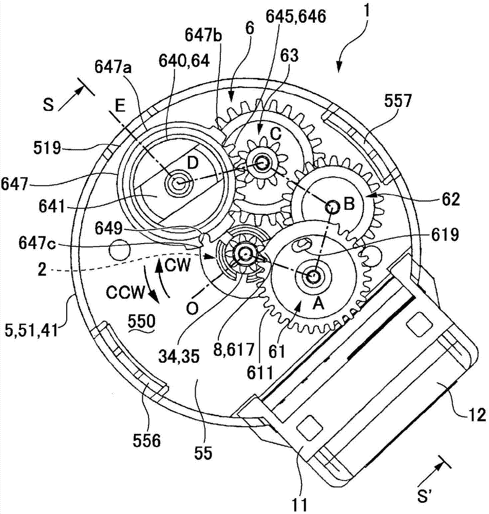
[0096] In the above embodiment, although the stopper 8 is provided on the input gear (gear 61 ), it may be provided on other gears 62 , 63 and the like.

[0097] In the above-mentioned embodiment, the stopper 8 is arranged on the gear mechanism 6 of the geared motor 1 with the motor 2 as the driving source, but the present invention can also be applied to the arrangement of the stopper 8 on the gear mechanism 6 driven by the motor 2 . The case on the gear mechanism 6 of the device other than the geared motor 1 of the source.

[0098] In the above-mentioned embodiment, on the stopper 8, the protruding part 617a is provided on two parts separated in the circumferential direction, and the recessed part 617b is provided on each of the protruding parts 617a at the two parts, but it is also possible A structure in which a continuous recess 617b is formed between the protrusions 617a provided at two locations is employed.

[0099] In the above embodiment, the first hole 649 and the ...


PUM


Abstract

The invention relates to a gear mechanism and a geared motor. Even though forming a limiting mechanism which utilizes the engagement of gears, a tooth part is not easy to damage. In the gear mechanism 6 and the geared motor 1, and when a motor small gear 34 (a first gear) and a gear ( a second gear ) are engaged to form the limiting mechanism, the limiting part comprising a tooth lacking part 617 not forming the tooth part 615 is arranged on the gear 61. In addition, the tooth lacking part 617 is equipped with a protruded part 617a protruded to an outer side in a radial direction with respect to a tooth tip circle F61 of the gear 61 and a recessed part 617b recessed to an inner side in the radial direction with respect to the protruded part 617a and adjacent to the protruded part 617a in a circumferential direction. Therefore, when the tooth part 345 of the electric small gear 34 is abutted against the recessed part 617b of the tooth lacking part (the limiting part), the protruded part 617a is abutted nearby the tooth tip circle P34 of the tooth part 345 of the electric small gear 34.

Description

technical field [0001] The invention relates to a gear mechanism and a gear transmission motor which utilize a plurality of gears to transmit force. Background technique [0002] In a gear mechanism configured in a geared motor or the like, when a stopper mechanism that limits the rotation angle range of the gear is provided, the engagement between the gears may be utilized. Specifically, in a gear mechanism having a first gear and a second gear meshing with the first gear, for example, a structure is proposed in which a valley portion sandwiched by teeth in the second gear is filled to form a stopper. (Refer to Patent Document 1). [0003] According to the above configuration, when the tops of the teeth of the first gear come into contact with the stoppers of the second gear, the first gear cannot rotate any further, and therefore, the rotation of the first gear can be stopped. [0004] prior art literature [0005] patent documents [0006] Patent Document 1: Japanese ...

Claims


Application Information

Patent Timeline
Patent Type & Authority Applications(China)
IPC IPC(8): F16H35/00F16H55/17H02K7/116
CPCF16H19/001F16H35/00F16H2019/008F16H2035/006H02K7/116Y10T74/19637Y10T74/19684Y10T74/19884F16H1/28F16H27/04F16H27/08
Inventor 山冈守
Owner SANKYO SEIKI MFG CO LTD
Features
  • R&D
  • Intellectual Property
  • Life Sciences
  • Materials
  • Tech Scout
  • Unparalleled Data Quality
  • Higher Quality Content
  • 60% Fewer Hallucinations
Learn More