
Continuously-adjustable sonic nozzle

A technology of sonic nozzle and valve body, applied in the direction of lift valve, valve details, engine components, etc., can solve the problems of difficult to change, cannot be used as a flow regulating device, and the flow is not easy to change, and achieves smooth transition, small operating force, and continuous flow. adjustable effects

Active Publication Date: 2013-04-10
NAT UNIV OF DEFENSE TECH
View PDF8 Cites 9 Cited by
  • Summary
  • Abstract
  • Description
  • Claims
  • Application Information

AI Technical Summary

Problems solved by technology

However, the profile of the current sonic nozzle is fixed, and the upstream air source pressure is generally not easy to change, and the flow rate is not easy to change at this time, so it cannot be used as a flow adjustment device.

Method used


Image

  • Continuously-adjustable sonic nozzle
  • Continuously-adjustable sonic nozzle
  • Continuously-adjustable sonic nozzle

Examples


Embodiment Construction

[0042] The embodiments of the present invention will be described in detail below with reference to the accompanying drawings, but the present invention can be implemented in many different ways defined and covered by the claims.

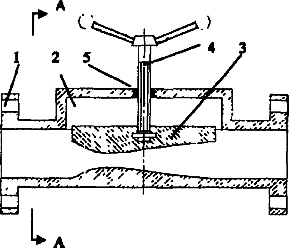
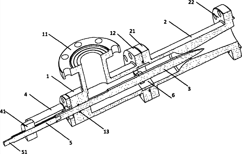
[0043] image 3 It is a schematic diagram of the overall structure of the present invention. The technical scheme adopted in the present invention is: adding a plug cone to the sonic nozzle with mature technology, and adjusting the throat area of ​​the sonic nozzle through the plug cone, so as to realize the continuous adjustment of the flow rate without changing the upstream area. The invention comprises a valve body 1, a sonic nozzle 2, a plug cone 3 and a transmission device.

[0044] Figure 4 It is a sectional view of the sonic nozzle 2. The sonic nozzle 2 is a rotary body, and the inner profile is a straight inlet section 24, a circular arc convergence section 25, a straight throat section 26, and a straight expansion section 27. All adopt...


PUM


Abstract

The invention provides a continuously-adjustable sonic nozzle, which comprises a valve body 1 and a sonic nozzle 2, wherein the valve body 1 is connected with the sonic nozzle 2; the sonic nozzle 2 is a body of revolution; and an inner molding surface is partitioned into an equal-diameter inlet section 24, a circular-arc-shaped contraction section 25, an equal-diameter throat section 26 and a linear expansion section 27. The continuously-adjustable sonic nozzle is characterized by further comprising a plug cone 3, wherein the plug cone 3 is a body of revolution; the front end of the plug cone 3 is conical; the inlet 11 and the outer 12 of the valve body 1 are non-colinear; the outlet 12 of the valve body, the sonic nozzle 2 and the plug cone 3 are coaxial; and the plug cone 3 moves along the axis of the sonic nozzle 2 to change the minimum flow area of the circular-arc-shaped contraction section 25. Continuous adjustment of flow is realized; and the continuously-adjustable sonic nozzle has the characteristics of simple structure, high flow adjusting accuracy, high repeatability, high hysteresis, small operation force and small interference to flow fields.

Description

technical field [0001] The invention relates to the technical field of gas flow regulation, in particular to a flow regulating valve. Background technique [0002] In many occasions in metallurgy, chemical industry and pneumatic industries, it is necessary to control and adjust the gas flow. The adjustment of gas flow is very important for automatic control. Therefore, regulating valves are widely used in industry. For the gas flow regulating valve, there are many researches at home and abroad, and the technology is relatively mature. [0003] Widely used in industry are butterfly valves, diaphragm valves, shutter control valves and other types. However, the adjustment of the flow by the current control valve is greatly affected by the downstream environment, and the degree of non-linearity of the flow adjustment is high. Ordinary flow regulating valve flow calculation is as follows: [0004] m · = KρA ...

Claims


Application Information

Patent Timeline
IPC IPC(8): F16K1/00F16K1/04F16K1/38F16K27/02F16K31/50
Inventor 李清廉成鹏赵天张建强郭浩儒陈慧源
Owner NAT UNIV OF DEFENSE TECH
Learn More