
Semicircular spliced LED (Light-Emitting Diode) lamp bulb provided with embedded driver

An LED light bulb and splicing technology, which is applied to the parts of lighting devices, semiconductor devices of light-emitting elements, lighting devices, etc., can solve the problems of low assembly efficiency, low welding efficiency, and high defect rate, and achieve high efficiency and reduce materials. and the effect of time wasted, uniqueness and reliability changes

Inactive Publication Date: 2013-04-10
咸阳金钻数码有限公司
View PDF6 Cites 1 Cited by
  • Summary
  • Abstract
  • Description
  • Claims
  • Application Information

AI Technical Summary

Problems solved by technology

[0012] The technical problem solved by the present invention is to provide a solution for the existing technical solution that the PCB driver assembly needs to use input and output leads, the welding efficiency is low, the defect rate is high, and the PCB driver assembly cannot be positioned, which leads to the insulation of the PCB driver assembly. Insulating sleeve or wrapping tape, the overall assembly efficiency is low, and the process consistency is difficult to control. Drive the built-in semicircle splicing LED bulb

Method used


Image

  • Semicircular spliced LED (Light-Emitting Diode) lamp bulb provided with embedded driver
  • Semicircular spliced LED (Light-Emitting Diode) lamp bulb provided with embedded driver
  • Semicircular spliced LED (Light-Emitting Diode) lamp bulb provided with embedded driver

Examples


Embodiment 1

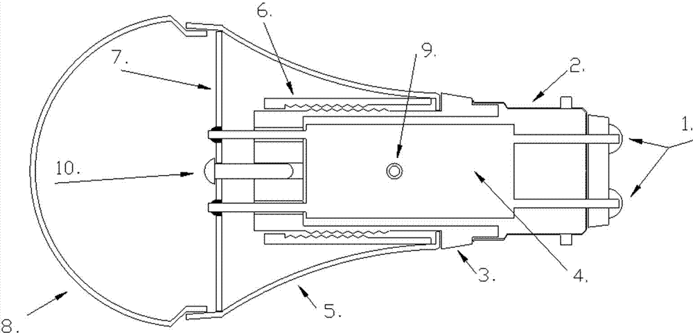
[0039] Example 1: see figure 1 , The two sets of connectors on the upper side of the PCB drive assembly 4 are arranged symmetrically along the center line of the PCB drive assembly 4. When the lamp holder 2 adopts the B22 model, the two sets of connectors on the lower side of the PCB drive assembly 4 are arranged horizontally and connected with the power terminal 1 of the lamp holder 2. Connect, and realize that the AC part of the PCB drive assembly 4 is introduced into the PCB body through the embedded lead wire to realize electrical conduction.

Embodiment 2

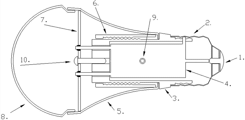
[0040] Example 2: see figure 2 , The two sets of joints on the upper side of the PCB drive assembly 4 are arranged symmetrically along the center line of the PCB drive assembly 4. When the lamp holder 2 adopts the E14, E26, E27 or E40 model, the back of the insulating housing 3 is provided with threads that match the threads of the lamp holder 2 Protruding ring, one of the sets of connectors on the lower side of the PCB drive assembly 4 is arranged horizontally and connected to the power terminal 1 of the lamp holder 2, and the other set of connectors is vertically penetrated in the threaded convex ring of the insulating housing 3 and connected to the lamp holder 2 The metal parts are locked and connected to realize electrical conduction.

Embodiment 3

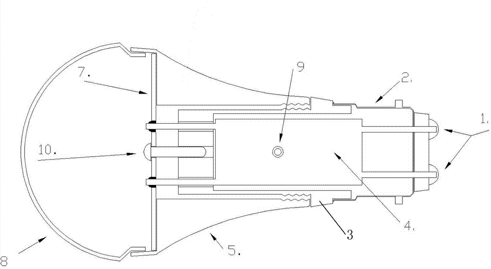
[0041] Embodiment 3: When the above-mentioned lamp holder 2 adopts the E14, E26, E27 or E40 model, the rear of the insulating housing 3 is provided with a threaded boss ring that matches with the lamp holder 2, and one set of joints on the lower side of the PCB drive assembly 4 is horizontal Set and connected with the power terminal 1 of the lamp holder 2, another set of joints is inserted in the threaded convex ring of the insulating housing 3 and wound on the threaded convex ring. The threaded convex ring of the insulating housing 3 is connected to the lamp holder 2. The metal parts are locked and connected to realize electrical conduction.


PUM


Abstract

The invention relates to a semicircular spliced LED (Light-Emitting Diode) lamp bulb provided with an embedded driver. A positioning hole is formed in a substrate of a PCB (Printed Circuit Board) driving assembly; an insulating shell consisting of two semicircular shells is sleeved outside the PCB driving assembly; the inner walls of the semicircular shells of the insulating shell are provided with positioning columns respectively; the positioning columns are inserted into the positioning hole; the lower part of the insulating shell is connected with a lamp cap; the upper part of the insulating shell is connected with the shell; a fastening sleeve is sleeved between the upper part of the insulating shell and the shell; both sides of the PCB driving assembly are provided with two groups of joints; the two groups of joints on the upper side are inserted into the top of the insulating shell, and are welded with a light source substrate; and two groups of joints on the lower side are connected with lamp cap. Due to the adoption of the semicircular spliced LED lamp bulb, leads for electrically connecting the PCB driving assembly, the lamp cap and an LED light source board are eliminated fully, the efficiency is increased greatly, and unnecessary waste of materials and work hours is reduced.

Description

Technical field [0001] The invention belongs to the technical field of LED bulbs, and relates to a semicircular splicing LED bulb with a built-in drive. Background technique [0002] The main structure of the existing LED bulbs is to adopt a screw installation method to pass the lamp cap of the bulb (such as B22, E27, E26, E40, etc.) through an insulated cylindrical plastic part and a metal bulb heat sink or a thermally conductive ceramic, Plastic heat sink connection. [0003] After connecting the lamp holder and the heat sink, the PCB driver assembly used to make the LED light source work is connected to the lamp holder by welding wires. At the same time, two leads are used to electrically connect the PCB driver assembly to the light source. [0004] Since the metal shell used for heat dissipation and the radiating plate of the LED light source are metal and are conductive materials, in order to ensure safety and insulation voltage, it is necessary to plug the PCB drive assembly i...

Claims


Application Information

Patent Timeline
Patent Type & Authority Applications(China)
IPC IPC(8): F21S2/00F21V23/06F21V17/10F21Y101/02F21K9/232F21K9/238F21Y115/10
Inventor 邱民
Owner 咸阳金钻数码有限公司
Learn More