
Design method of buried heat exchange system

A technology of heat exchange system and design method, which is applied in the field of design of buried heat exchange system, can solve the problems of increasing energy consumption and the failure of the system to achieve energy saving, and achieve the effects of improving rationality, facilitating design calculations, and simplifying design methods

Active Publication Date: 2015-04-29
HUA HUI ENGINEERING DESIGN GROUP CO LTD
View PDF3 Cites 0 Cited by
  • Summary
  • Abstract
  • Description
  • Claims
  • Application Information

AI Technical Summary

Problems solved by technology

[0006] However, at present, there are many problems with ground source heat pumps in actual projects, even in the first operating season. Different degrees of heat / cold accumulation can cause the system to fail to achieve the purpose of energy saving, and in severe cases, it will increase energy consumption

Method used


Image

  • Design method of buried heat exchange system

Examples


Embodiment 1

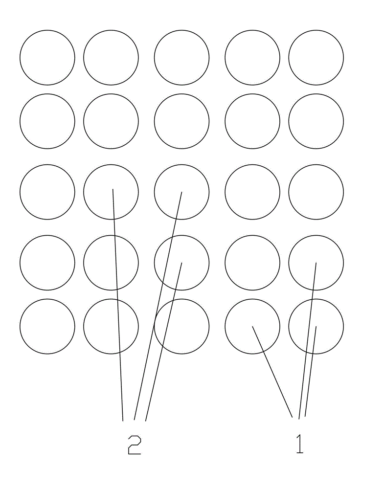
[0021] like figure 1 As shown, this embodiment provides a design method for a buried pipe ground source heat pump system, including the following steps:

[0022] First, the distance d of the buried pipe heat exchanger is calculated according to the buried area of ​​the buried heat exchange system, and the distance between the outermost buried pipe 1 is 0.9 times the distance between the inner buried pipes 2 when buried. The distance d of the buried tube heat exchanger is calculated by the formula: d=L / 2(n+0.9), and d should be within 3~6m; where L is the buried area of ​​the buried heat exchange system, and n is Buried thermal array row number.

[0023] Second, according to the layout distance d of the buried pipe heat exchanger and the thermal and physical parameters of the rock and soil, it is estimated by the following calculation formula:

[0024] Q'(d,c,λ)=-0.019d 2 cΔt-0.0031dc 2 Δt+0.12dcΔt+0.023d 2 Δt+0.011d 2 cλΔt-0.052dcλΔt-0.036d 2 λΔt-0.0083c 2 λΔt+0.3dλΔt+...


PUM


Abstract

The invention discloses a design method of a buried heat exchange system. The design method comprises the following steps of: (1) calculating a space d between buried pipe heat exchangers according to a burying region of the buried heat exchange system, and taking the space between buried pipes (1) on the outermost layer as 0.9 times of the space of the inner buried pipes during burying; (2) next calculating an equivalent heat exchange capacity design value of the buried pipe heat exchangers under the action of dynamic load according to the space d of the buried pipe heat exchangers and a rock-soil thermo-physical property parameter; and (3) calculating the depth of the buried pipes of each buried pipe heat exchanger by dividing a building load demand total value by the equivalent heat exchange capacity design value to obtain an actual depth value of the buried pipes so as to finish design of the entire buried heat exchange system. According to the design method, the heat exchange capacity design calculation of the buried pipes of a ground source heat pump system is greatly simplified, the scientificity and the rationality of the buried heat exchange system are improved, and one-time investment of the system can be reduced.

Description

technical field [0001] The invention relates to a design method of an underground heat exchange system. Background technique [0002] The ground source heat pump system is a high-efficiency energy-saving air-conditioning system that utilizes surface shallow heat sources. It has the characteristics of regeneration and can achieve the purpose of energy saving and emission reduction. The ground source heat pump system uses rock and soil, groundwater or surface water as the low-temperature heat source, and consists of a heating and air conditioning system composed of a ground source heat pump unit, a geothermal energy exchange system, and a building system. According to the different forms of geothermal energy exchange systems, ground source heat pump systems are divided into buried pipe ground source heat pump systems, groundwater ground source heat pump systems and surface water ground source heat pump systems. [0003] Among them, the buried heat exchange system is to drill ...

Claims


Application Information

Patent Timeline
Patent Type & Authority Patents(China)
IPC IPC(8): G06F17/50
Inventor 娄荣沈光明肖景平陈威文
Owner HUA HUI ENGINEERING DESIGN GROUP CO LTD
Learn More