Hydraulic System For Central Lubrication Of Engine Cylinders

A technology of engine cylinder and hydraulic system, applied in the direction of controlling lubricant pressure, piston fluid pressure measurement, electrical components, etc., can solve leakage and other problems, and achieve the effect of avoiding damage

Active Publication Date: 2013-04-10
HANS JENSEN LUBRICATORS
View PDF11 Cites 4 Cited by
  • Summary
  • Abstract
  • Description
  • Claims
  • Application Information

AI Technical Summary

Problems solved by technology

[0024] Between the overhauls / inspections mentioned there may be a leak for a short or long period until the next inspection which can cause an unacceptable low pressure in the lubricating oil

Method used


Image

  • Hydraulic System For Central Lubrication Of Engine Cylinders
  • Hydraulic System For Central Lubrication Of Engine Cylinders
  • Hydraulic System For Central Lubrication Of Engine Cylinders

Examples


Embodiment Construction

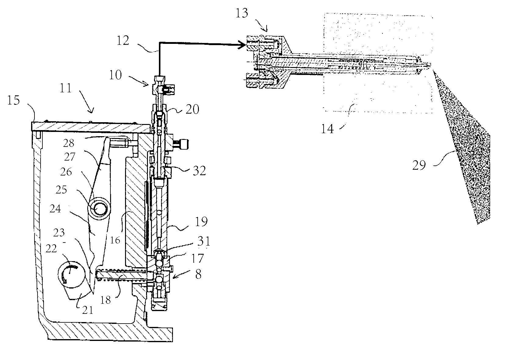
[0058] exist figure 1 , 2 The lubricating device 11 is illustrated in and 3 . The illustrated lubricating device has a box-shaped device housing 15 carrying on a front wall 16 a series of reciprocating pump assemblies 8, only one of which is shown here. The assembly has a valve housing 17 with a lower inlet for lubricating oil, a middle part for receiving the piston 18 protruding into the housing 15, and an upper outlet 31 for thus forming reciprocating pump. This outlet 31 is connected to the upper connection stud 20 through a flow indicator 19 and a channel 30 in a plate 32 . A plurality of connecting pipes originate from the entire row of these stubs and are distributed to the respective lubricating points of the cylinders of the engine, eg numbered 6-24.

[0059] The piston 18 is driven for pressurization by means of a drive tappet 21 on an all-through control shaft 22 which rotates synchronously with the crankshaft of the engine and rests on a bearing housing in the d...


PUM


Abstract

There is disclosed a hydraulic system for cylinder lubrication of engine cylinders in large diesel engines, in particular marine engines, by injection of oil. The system is designed with injectors (13) and a lubricating apparatus (11) which includes a number of pump units (8). Each pump unit (8) is connected with an associated injector (13) via a connecting pipe (12). In the connecting pipe (12), between a pump unit and an associated system unit a leak detector (10) is provided, adapted for emitting a signal when the oil pressure in the connecting pipe (12) go under a predetermined level. Hereby is achieved a reliable, technically simple and cheap system for leak monitoring which enables continuous monitoring of leakage with running engine so as to ascertain if one or more injectors (13) are leaking.

Description

technical field [0001] The invention relates to a hydraulic system, preferably a central lubricating system for cylinder lubrication of engine cylinders by means of oil injection in large diesel engines, especially marine engines, designed with injectors and lubricating means , the system includes at least one pump assembly, which is connected to a selected corresponding system component between the syringe and the reservoir through a connecting tube. [0002] In addition to central lubrication systems, the invention can be applied to other hydraulic systems. The invention is therefore applicable to all hydraulic systems in which the system components are in the form of injectors and / or accumulators. [0003] The term used in this application: system components refers to the hydraulic components connected with the pump. It can be a syringe, which injects oil from the pump, or it can be an accumulator, which is connected to the pump to equalize pressure fluctuations for subse...

Claims


Application Information

Patent Timeline
Patent Type & Authority Applications(China)
IPC IPC(8): F01M1/16G01L7/16H01H35/38
CPCF01M1/16G01L7/16H01H35/38
Inventor 皮尔·巴克
Owner HANS JENSEN LUBRICATORS
Why Eureka
Try Eureka