Closed pulse dust collector and dust collection method thereof

A pulse dust collector and closed technology, applied in chemical instruments and methods, separation methods, dispersed particle separation, etc., can solve problems such as inability to automatically and effectively remove dust, and achieve the effect of obvious dust removal effect and improved dust removal effect.

Active Publication Date: 2013-04-17
GUANGXI DADU CONCRETE GROUP
View PDF4 Cites 13 Cited by
  • Summary
  • Abstract
  • Description
  • Claims
  • Application Information

AI Technical Summary

Problems solved by technology

[0006] The present invention aims at the disadvantage that the gas ejected from the blowing pipe communicates with the atmosphere through the air outlet in the existing pulse dust collector and cannot automatically and effectively remove dust, and provides a closed pulse dust collector and its dust removal method to solve the above problems

Method used


Image

  • Closed pulse dust collector and dust collection method thereof
  • Closed pulse dust collector and dust collection method thereof

Examples


Embodiment 1

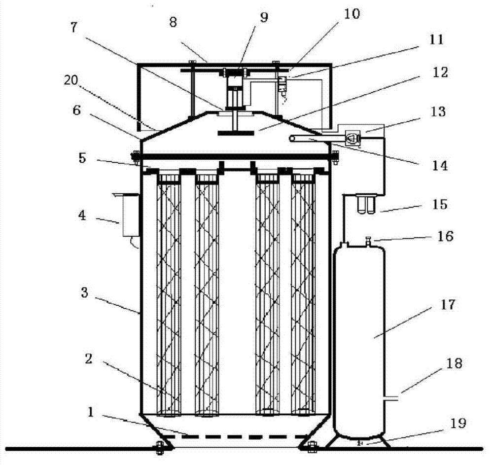
[0031] like figure 1 As shown, in the closed pulse dust collector in the present invention, the dust collector housing 3 is provided with a safety net 1 at the bottom of the dust collector housing 3, and a power control box 4 is provided at the side of the dust collector housing 3, and a dust removal filter element 2 The filter element fixing plate 5 is arranged inside the dust collector housing 3, the top position of the dust removal filter element 2 is provided with a sealing chamber cover 8, the dust removal filter element 2 is connected with the sealing chamber cover 6, and the top of the sealing chamber cover 6 is provided with an air outlet 7, and at the air outlet 7 is provided with a valve plate 12 that can be lifted up and down. The lifting of the valve plate 12 can control the opening or closing of the air outlet 7. The connecting rod of the valve plate 12 is connected with the cylinder 9. The electromagnetic pneumatic valve 11 controls the expansion and contraction o...

Embodiment 2

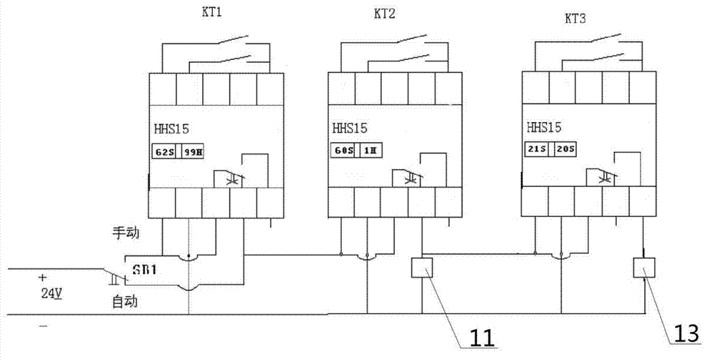
[0035] The difference from Embodiment 1 is that the diameter of the connecting air pipe between the air injection pipe 14, the air storage tank 17 and the air dryer 15 is 60mm, and the SB1 during dust removal is activated to the manual state, that is, after KT1 is energized, KT2 is connected. Pass through the electromagnetic pneumatic valve 11 to make the cylinder 9 push the valve plate 12 to close the air outlet 7 for a total of 80 seconds, and then after the valve plate 12 is closed for 15 seconds, the pulse pneumatic valve 13 will blow air for a total of 15 seconds, and then the valve plate 12 In the closed state for 50 seconds, the air pressure can be balanced in the sealed chamber cover 6. After the operation is completed, switch KT1 to the power-off state. At this time, KT2 and KT3 are also in the power-off state. The cleaning work is completed, and the above-mentioned cleaning work belongs to manual operation. The rest of the working principles are the same as in Embodi...

Embodiment 3

[0037] The difference from Example 1 is that the diameter of the connecting air pipe between the air injection pipe 14, the air storage tank 17 and the air dryer 15 is 50mm, and the dust removal method is that when SB1 is switched to the automatic gear, KT2 is energized Start the electromagnetic pneumatic valve 11 to push the cylinder 9 to pull up the valve plate 12 to close the air outlet 18 of the sealing chamber. Among them, the command issued by KT2 to the electromagnetic pneumatic valve 11 is to close the valve plate 12 for 70 seconds. When the valve plate 12 is closed, KT3 gets The instruction is to keep the air pressure stable after the valve 12 is closed for 19 seconds, and the pulse pneumatic valve 13 starts blowing, and the blowing time is 18 seconds, and the dust removal work is carried out on the dust removal filter element 2. After the blowing is finished, the valve plate 12 Keep it closed for 33 seconds, so that the air pressure in the sealing chamber cover 6 is s...


PUM

PropertyMeasurementUnit
diameteraaaaaaaaaa

Abstract

The invention discloses a closed pulse dust collector and a dust collection method thereof. The closed pulse dust collector comprises a dust collector housing (3), wherein dust collection filter elements (2) are arranged in the dust collector housing (3). The closed pulse dust collector is characterized in that a sealed chamber cover (6) is arranged at the tops of the dust collection filter elements (2); the dust collection filter elements (2) are connected with the sealed chamber cover (6); an air outlet (7) is formed at the top of the sealed chamber cover (6); a valve plate (12) controlling the opening and closing of the air outlet (7) is arranged at the air outlet (7); and an air ejection pipe (14) connected with a pulse pneumatic valve (13) is arranged at the side part of the sealed chamber cover (6). According to the invention, the air outlet is closed automatically under the control of a power supply control box; an opposite sealed chamber is formed by the sealed chamber cover and the dust collector filter elements; air ejected by the air ejection pipe forms a pressure air mass to act on the dust collection filter elements, so that a dust collection effect is improved by above 20% compared with the prior art.

Description

technical field [0001] The invention relates to a cement silo dust collector, in particular to a closed pulse dust collector and a dust removal method thereof. Background technique [0002] With the improvement of social living standards, the environmental protection requirements for urban construction are also getting higher and higher; the promotion of bulk cement, the development of ready-mixed commercial concrete mixing stations, and the application of cement silos for storing powdery materials are also becoming more and more extensive. , so the environmental protection requirements for cement silos are getting higher and higher. At present, the dust collectors used on cement silos generally adopt the dust removal method of filter element filtration, and the self-maintenance of the filter elements of the dust collector mainly includes pulse blowback, vibration or vibration + Back blowing and other three ways. As shown in the existing blowback dust collector, it consists...

Claims


Application Information

Patent Timeline
Patent Type & Authority Applications(China)
IPC IPC(8): B01D46/04B01D46/42
Inventor 韦炳军蒙飞丞李志雄雷振宁陆乔陆路
Owner GUANGXI DADU CONCRETE GROUP
Why Eureka
Try Eureka