Connecting ring cutter paper shredder and paper shredding method of paper shredder

A paper shredder and paper shredding technology, which is applied in the direction of grain processing, etc., can solve the problems of unstable connection between the blade and the knife shaft, increase the process and cost, and cannot be integrally formed, and achieve the effect of simple structure, convenient operation, and low cost

Active Publication Date: 2013-04-17
DONGGUAN ELITE ELECTRIC HARDWARE PRODUCT CO LTD
View PDF6 Cites 3 Cited by
  • Summary
  • Abstract
  • Description
  • Claims
  • Application Information

AI Technical Summary

Problems solved by technology

[0003] However, this type of shredding cutter needs to cut the paper into shreds, and the shredding blade must be provided with several blade points, and the processing of the blade points makes this type of shredding blade must be manufactured by stamping or after the blade is processed. After shoveling out the tip of the knife, not only the process is complicated, but also the blade and the knife shaft must adopt a split structure, which cannot be integrally formed, which further increases the process and cost, and there is a problem of unstable connection between the blade and the knife shaft
For this reason, the prior art d

Method used


Image

  • Connecting ring cutter paper shredder and paper shredding method of paper shredder
  • Connecting ring cutter paper shredder and paper shredding method of paper shredder
  • Connecting ring cutter paper shredder and paper shredding method of paper shredder

Examples


Embodiment Construction

[0039] In order to describe the technical content, structural features, achieved goals and effects of the present invention in detail, the following will be described in detail in conjunction with the embodiments and accompanying drawings.

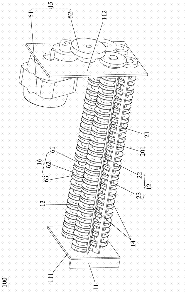
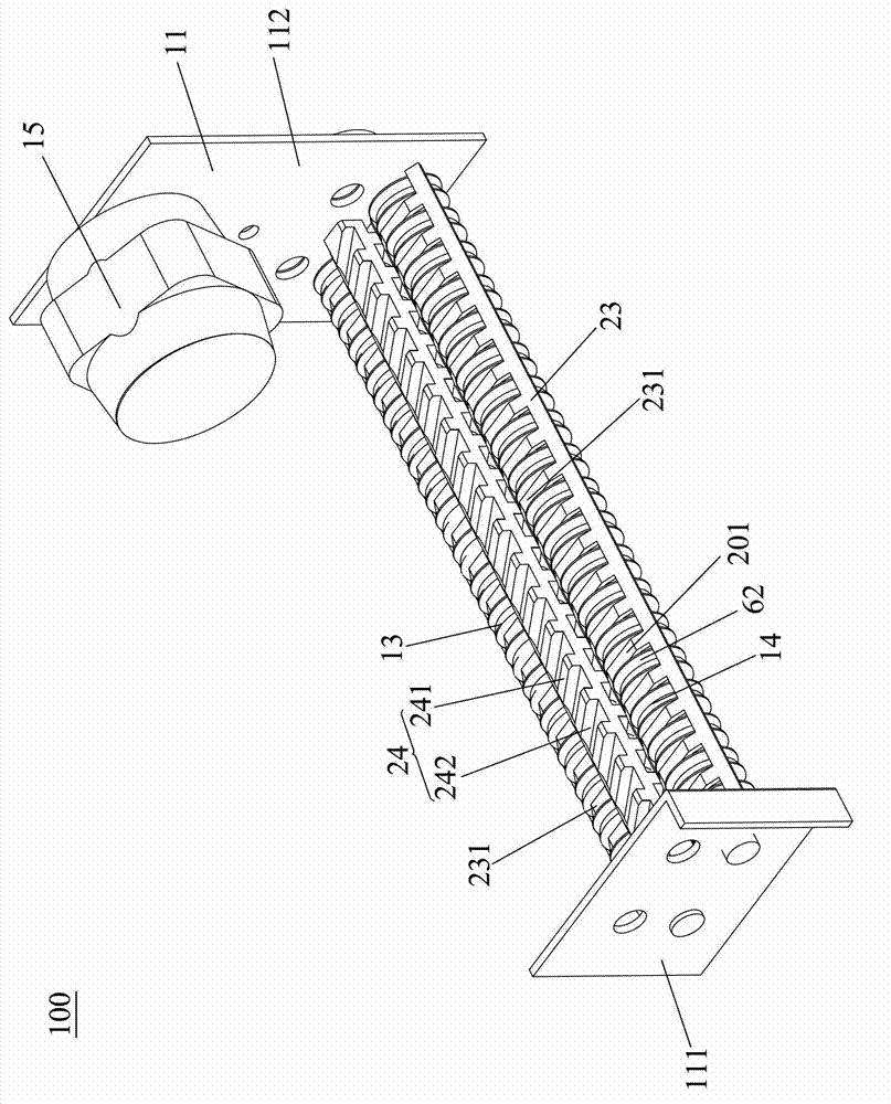
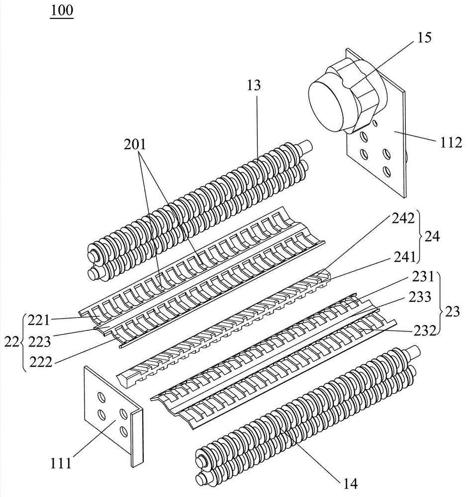
[0040] refer to Figure 1 to Figure 6 , discloses the first embodiment of the serial knife shredder of the present invention, refer to figure 1 and figure 2 , the chain knife shredder 100 includes a frame 11, a first shredder mechanism 13 installed on the frame 11, a second shredder mechanism 14 and a drive mechanism 15, the drive mechanism 15 is connected to the first The shredding mechanism 13 and the second shredding mechanism 14 are connected and control the first shredding mechanism 13 and the second shredding mechanism 14 to shred paper, and the first shredding mechanism 13 and the second shredding mechanism 14 are strip shaped shredder mechanism, refer to figure 2 and Figure 4 , the paper outlet of the first shredding mechani...


PUM


Abstract

The invention provides a connecting ring cutter paper shredder which comprises a rack, and a first paper shredding mechanism, a second paper shredding mechanism and a driving mechanism which are arranged on the rack, wherein the driving mechanism is respectively connected with the first paper shredding mechanism and the second paper shredding mechanism and drives the first paper shredding mechanism and the second paper shredding mechanism to shred a paper; the first paper shredding mechanism and the second paper shredding mechanism are strip-shaped paper shredding mechanisms; a paper outlet of the first paper shredding mechanism is communicated with a paper inlet of the second paper shredding mechanism; and an acute angle is available between a paper transmitting direction of the paper inlet of the second paper shredding mechanism and the axial direction of a cutter shaft of the second paper shredding mechanism. When the paper is shredded, the first paper shredding mechanism is used for cutting the paper into a plurality of fine paper tapes at the same time, and a second paper shredding cutter is used for inwards and slantwise cutting off the plurality of fine paper tapes into shredded paper particles along one side of the second paper shredding mechanism at the acute angle, so that the paper is labor-saving and high-efficiency to shred. Furthermore, the invention further provides a paper shredding method of the paper shredder.

Description

technical field [0001] The invention relates to the field of paper shredding, in particular to a chain-knife shredder using a two-piece shredding mechanism to cut paper and a corresponding paper shredding method. Background technique [0002] At present, in daily life or work, there are often documents that need to be destroyed, so as to prevent others from obtaining the information recorded on the documents. The shredder mainly uses relatively rotating shredding cutters to cut paper into thin paper strips or shreds. A traditional paper shredding cutter includes a knife shaft and a group of shredding blades fixed on the knife shaft in series. The paper shredding blade includes a knife body and several knife points formed on the edge of the knife body. The knife shaft rotates at the same time to squeeze the paper, so that the paper is cut into thin paper strips by the body of the shredding blade on the knife shaft, and the thin paper strips are cut into shreds by the tip of ...

Claims


Application Information

Patent Timeline
IPC IPC(8): B02C18/14B02C18/18
CPCB02C18/0007
Inventor 陆觅贇
Owner DONGGUAN ELITE ELECTRIC HARDWARE PRODUCT CO LTD
Why Eureka
Try Eureka