Spindle turning error source tracing method based on shaft center orbit manifold learning

A technology of axis trajectory and rotation error, which is applied to metal processing machinery parts, maintenance and safety accessories, measurement/indicating equipment, etc., to achieve the effect of improving service reliability, accuracy reliability and production efficiency

Active Publication Date: 2013-04-17
BEIJING INFORMATION SCI & TECH UNIV
View PDF5 Cites 13 Cited by
  • Summary
  • Abstract
  • Description
  • Claims
  • Application Information

AI Technical Summary

Problems solved by technology

The two are separated and independent from each other, and cannot provide real-time evaluation and judgment of accuracy degradation for actual on-site production

Method used


Image

  • Spindle turning error source tracing method based on shaft center orbit manifold learning
  • Spindle turning error source tracing method based on shaft center orbit manifold learning
  • Spindle turning error source tracing method based on shaft center orbit manifold learning

Examples


Embodiment Construction

[0015] The present invention will be described in detail below in conjunction with the accompanying drawings and embodiments.

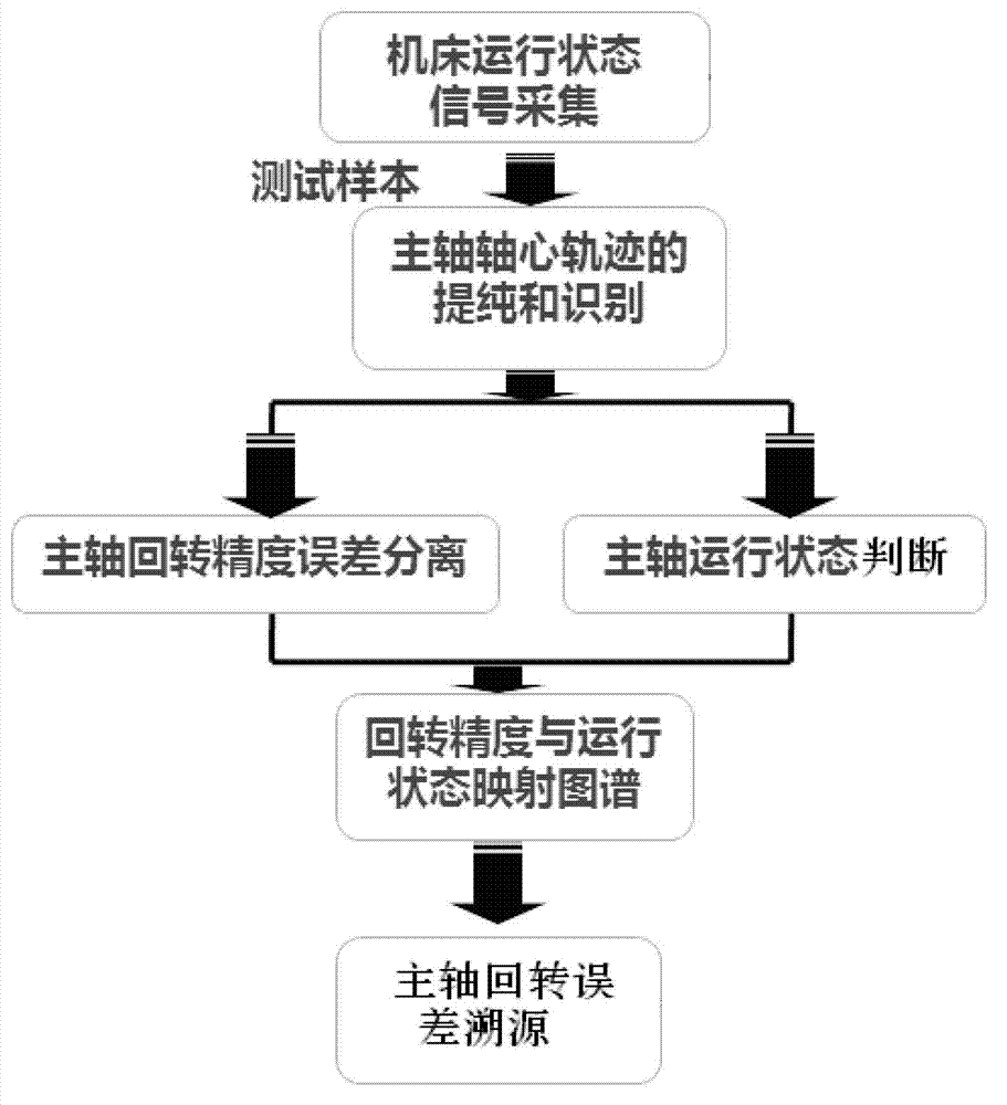
[0016] like figure 1 As shown, the present invention provides a method for tracing the source of the spindle rotation error based on the learning of the axis trajectory manifold, which includes the following steps:

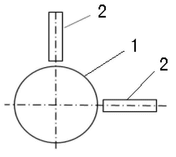
[0017] 1) Two eddy current sensors 2 are arranged at intervals in the outer circumferential direction of the main shaft 1, and the two eddy current sensors 2 are arranged staggered at 90° along the axis of the main shaft 1 (such as figure 2 As shown), the vibration signal of the main shaft 1 is collected by two eddy current sensors 2.

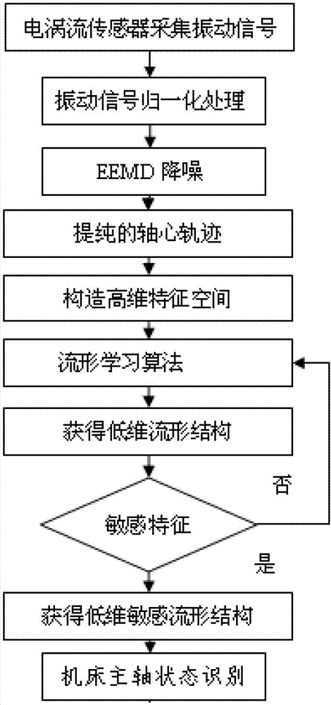
[0018] 2) Process the detected vibration signal of the spindle, and then judge the running state of the spindle 1 (such as image 3 shown), which includes the following steps:

[0019] (1) Mark the vibration signals measured by two eddy current sensors 2 arranged staggered at 90° as X and Y respectivel...


PUM


Abstract

The invention relates to a spindle turning error source tracing method based on shaft center orbit manifold learning. The method includes the following step that (1) two electrical vortex sensors are arranged on the periphery of a spindle at intervals and used for collecting spindle vibration signals; (2) the detected spindle vibration signals are processed to judge an operation state of the spindle; (3) the spindle vibration signals intersect at one point on the same plane, and a shaft center orbit is obtained after continuous sampling; (4) error separation is conducted on a spindle center orbit to obtain spindle actual rotation precision A; (5) a mapping function atlas data base Q:{f(i)=Qij|A} is obtained according to the spindle actual rotation precision A and a manifold sensitive characteristic Qij; and (6) if the spindle actual rotation precision A>=etaE, eta=0.8-1, the mapping function atlas data base Q is called, source tracing of spindle rotation errors is conducted, and corresponding faults are maintained; and if the spindle actual rotation precision A>=etaE, eta=0.6-0.8, source tracing analysis monitoring is conducted on the spindle rotation errors, wherein E is spindle rotation precision of a machine tool leaving a factory.

Description

technical field [0001] The invention relates to a method for tracing the source of the spindle rotation error of electromechanical equipment, in particular to a method for tracing the source of the spindle rotation error based on the learning of the axis trajectory manifold. Background technique [0002] With the development of emerging science and technology such as atomic energy, aerospace technology, microelectronics, information technology and bioengineering, the requirements for machining precision are getting higher and higher, from millimeters to microns and sub-microns, and now it has developed to the nanometer level, and Gradually moving towards the atomic lattice size (sub-nanometer) level, it is called ultra-precision machining. Precision machine tools are the primary basic conditions for precision machining. At present, high-speed ultra-precision CNC machine tools have become the key production equipment of modern manufacturing industry. Improving the reliabilit...

Claims


Application Information

Patent Timeline
Patent Type & Authority Applications(China)
IPC IPC(8): B23Q17/12B23Q11/00
Inventor 王红军韩秋实徐小力谷玉海
Owner BEIJING INFORMATION SCI & TECH UNIV
Why Eureka
Try Eureka