Voltage source converter

a voltage source converter and voltage source technology, applied in the direction of motor/generator/converter stopper, dynamo-electric converter control, pulse technique, etc., can solve the problems of increasing the cost of installation of additional chokes, over-engineering of diode rectifiers for continuous operation, and requiring a fair amount of spa

Inactive Publication Date: 2007-07-31
SIEMENS AG
View PDF15 Cites 8 Cited by
  • Summary
  • Abstract
  • Description
  • Claims
  • Application Information

AI Technical Summary

Benefits of technology

[0013]By using the topology according to the invention for a voltage source converter, the power supply is decoupled from the slim DC link of the DC link converter, so that depending on the sizing of the buffer capacitor, power to the electronics of the pulsed inverter can be maintained in the event of a line failure. When the line voltage returns, only a small recharging current flows due to the relatively small capacitance value of the DC link capacitor. This small recharging current does not cause I2T loading of the diodes of the line-side rectifier, so that the diode rectifier of the DC link converter no longer needs to be over-engineered.
[0014]As a result, the voltage source converter has an increased service reliability even in unstable power grids, without adding complexity to its line power input.

Problems solved by technology

However, such diode rectifier would be over-engineered for the power required for continuous operation.
However, installing an additional choke disadvantageously adds to the cost and also requires a fair amount of space.
However, the motor then disadvantageously requires a more than 10% greater motor current under normal operating conditions, which increases the motor temperature.
However, this causes the power supply to fail in the event of line power interruptions, so that the operation of the frequency converter cannot be continued.
This requires a special configuration of the power supply which also tends to be more costly.
Line power interruptions are more frequent in countries that have unstable power grids.
Because it is difficult in most cases to predict the line conditions ahead of time, substantial design work is required to dimension such choke.
Otherwise, the frequency converter may fail.
If a frequency converter with a slim DC link is connected to an unstable power grid, failures of the frequency converter cannot be prevented even when using buffered power supplies and kinetic buffering.

Method used


Image

  • Voltage source converter
  • Voltage source converter

Examples


Embodiment Construction

[0019]The depicted embodiment is to be understood as illustrative of the invention and not as limiting in any way. It should also be understood that the drawing is not necessarily to scale and that the embodiment may be illustrated by graphic symbols, phantom lines, and / or diagrammatic representations. Details which are not necessary for an understanding of the present invention or which render other details difficult to perceive may have been omitted.

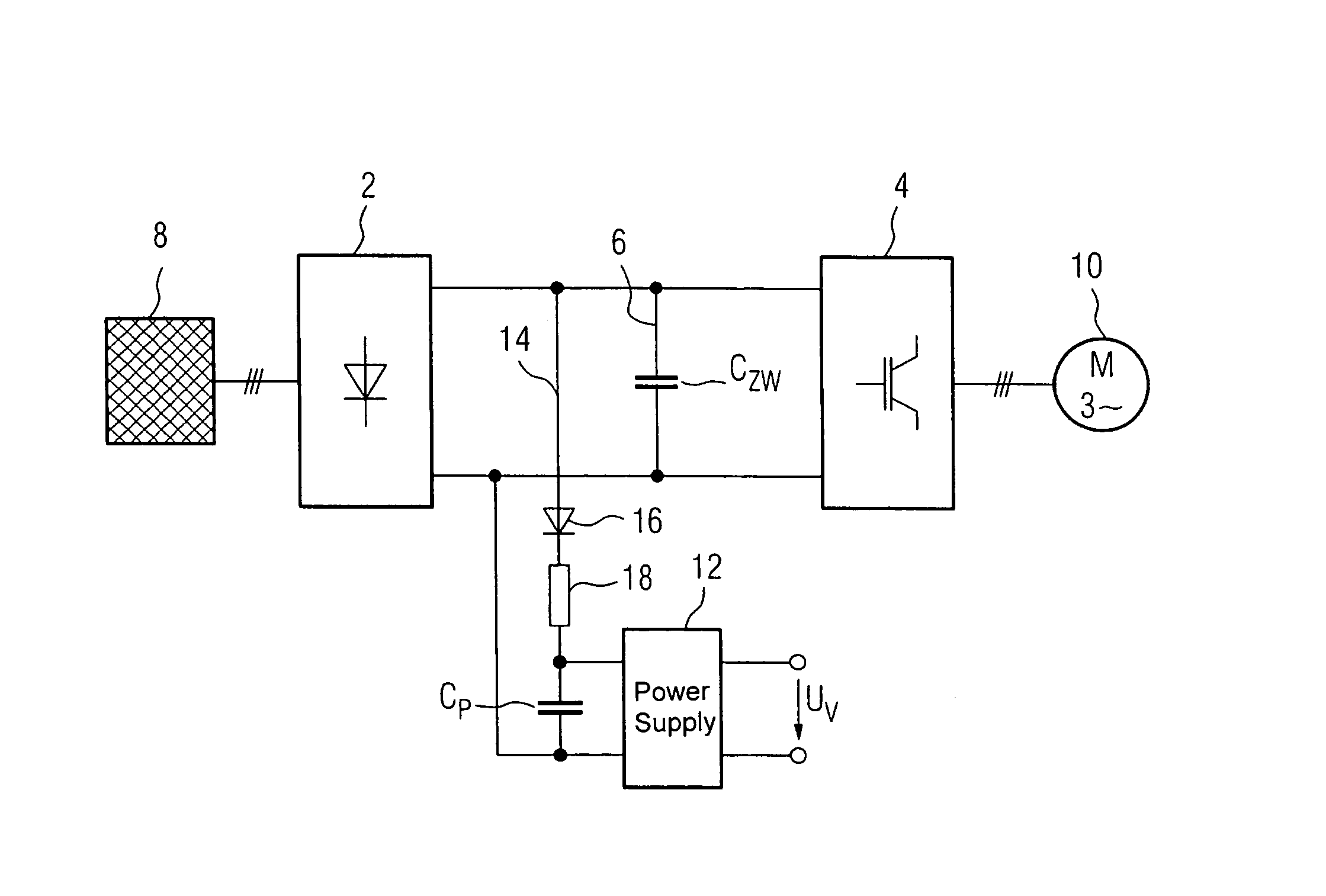
[0020]Turning now to the only FIGURE, a voltage source converter according to the invention includes a line-side converter 2 and a load-side inverter 4, which are electrically connected with each other on their respective DC side by a slim DC link 6. The line-side converter 2 is implemented as a diode rectifier, whereas the load-side inverter 4 is implemented as a pulsed inverter. The slim DC link 6 can include, for example, a foil capacitor as a DC link capacitor CZW. A power grid 8 is connected to line input terminals of the converte...


PUM


Abstract

A voltage source converter with a line-side diode rectifier, a load-side inverter with an electronic circuit, a power supply for the electronic circuit, and a slim DC link with a DC link capacitor is described. The slim DC link connects a DC output side of the line-side diode rectifier with a DC input side of the load-side inverter. A buffer capacitor is connected across the power supply, and a decoupling diode and a current limiting circuit are electrically connected in series with the buffer capacitor. The serially connected buffer capacitor, decoupling diode and current limiting circuit are connected in parallel with the DC link capacitor. This arrangement results in a voltage source converter that has an improved service reliability even in unstable power grids, without adding circuit complexity to the line input.

Description

CROSS-REFERENCES TO RELATED APPLICATIONS[0001]This application claims the priority of German Patent Application, Serial No. 103 38 476.6, filed Aug. 21, 2003, pursuant to 35 U.S.C. 119(a)-(d), the disclosure of which is incorporated herein by reference.BACKGROUND OF THE INVENTION[0002]The invention relates to a voltage source converter with a line-side diode rectifier, a slim DC link and a power supply for the electronics of a load-side inverter of this converter.[0003]Commercially available voltage source converters, also referred to as frequency converters, have converters on both the line side and the load side which are connected with one another on their respective DC side by a voltage DC link. The line-side inverter is implemented as a line-commutated converter, for example a diode rectifier, while the load-side converter is implemented as a self-commutated converter, for example a pulsed inverter. The voltage DC link includes one or more electrolytic capacitors. Moreover, a f...

Claims


Application Information

Patent Timeline
Patent Type & Authority Patents(United States)
IPC IPC(8): H03K3/00H02M5/27H02M5/458
CPCH02M5/271H02M5/458
Inventor FRANKE, RALF-MICHAELIMRICH, FRANZ
Owner SIEMENS AG
Why Eureka
Try Eureka