Supercharge Your Innovation With Domain-Expert AI Agents!

Hydraulic lift mechanism for prestressed concrete slab forming machine

A plate forming machine and hydraulic lifting technology, applied in the field of lifting mechanism, can solve the problems of low efficiency, time-consuming and laborious, troublesome, etc., and achieve the effects of small turning radius, labor-saving and light operation, and simple structure.

Inactive Publication Date: 2013-04-17
河南四海建材设备有限公司
View PDF7 Cites 3 Cited by
  • Summary
  • Abstract
  • Description
  • Claims
  • Application Information

AI Technical Summary

Problems solved by technology

The current method is that several people use a crowbar to pry up the machine at the same time, install steering wheels on the front end of the machine, install lifting wheels on the rear of the machine, pull the machine to the station, and then use the crowbar to pry the machine up to remove the The steering wheel at the front of the machine and the lifting wheel at the rear of the machine are very troublesome, time-consuming and labor-intensive, and inefficient

Method used


Image

  • Hydraulic lift mechanism for prestressed concrete slab forming machine
  • Hydraulic lift mechanism for prestressed concrete slab forming machine
  • Hydraulic lift mechanism for prestressed concrete slab forming machine

Examples


Embodiment 1

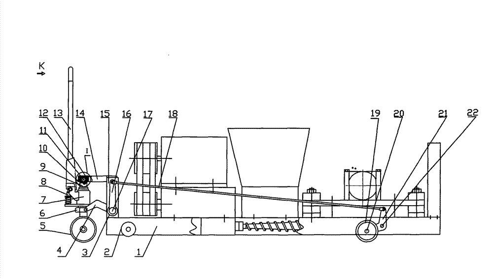
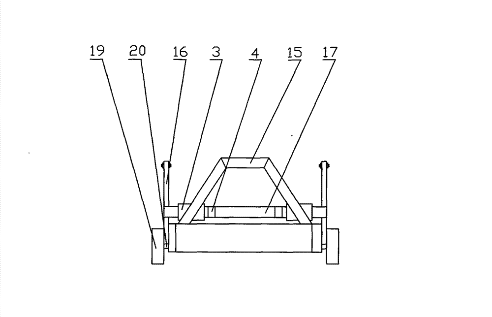
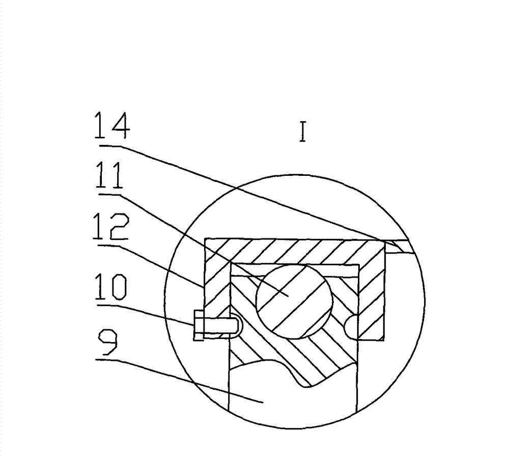
[0026] Example 1: Such as figure 1 , figure 2 , image 3 , Figure 4 As shown, the hydraulic lifting mechanism of the prestressed concrete hollow floor extrusion molding machine includes a frame 1, a walking wheel 2 rotatably connected on both sides of the front of the frame 1, and a vertical hydraulic lifting device provided at the front end of the frame. A support frame 15 is fixedly connected to the upper surface of the front end of the frame, and a fixed sleeve 3 is fixedly connected to the lower part of the support frame 15. A lifting rotating shaft 17 that can rotate in the fixed sleeve passes through the fixed sleeve 3. The two ends of the shaft 17 are fixedly connected with a rotating arm 16; the lifting and rotating shaft 17 is fixedly connected with a front knee arm 4, and the other end of the front knee arm 4 is connected to the support seat 6 in the vertical hydraulic lifting device. Hinge; the upper end of the support frame 15 is fixedly connected with a top plate...

Embodiment 2

[0032] Example 2: Example 2 has basically the same structure as Example 1, except that the prestressed concrete hollow floor extrusion molding machine is replaced with a prestressed concrete hollow floor extrusion molding machine. Others are the same as in Example 1.

Embodiment 3

[0033] Embodiment 3: The structure of Embodiment 3 is basically the same as that of Embodiment 1, except that the prestressed concrete hollow slab extrusion molding machine is replaced by a prestressed concrete hollow stair stepping extrusion molding machine. Others are the same as in Example 1.


PUM


Abstract

The invention discloses a hydraulic lift mechanism for a prestressed concrete slab forming machine. The hydraulic lift mechanism comprises a rack and a vertical hydraulic lifting device which is arranged at the front end of the rack. The front end of the rack is fixedly connected with a support frame, the lower portion of the support frame is fixedly connected with a fixing sleeve, a lift rotating shaft passes through the fixing sleeve and can rotate in the fixing sleeve, and both ends of the lift rotating shaft are fixed connected to a rotating arm. The outside surface of the tail end of the rack is correspondingly fixedly connected with two crank shafts which are rotationally connected with a crank arm; and the lower end of the crank arm is fixedly connected with a lifting axle which is drivingly connected with a lifting wheel. The upper end of the crank shaft is hinged to a lever; and the other end of the lever is hinged to the upper end of the rotating arm. The hydraulic lift mechanism is directly connected to the rack, the trouble of frequent loading and unloading is eliminated. By means of hydraulic lift, the lifting is smooth and steady, the turning radius is small, the operation is effortless and the safety is reliable.

Description

Technical field [0001] The invention relates to a lifting mechanism of building material forming equipment, in particular to a hydraulic lifting mechanism of a prestressed concrete slab forming machine. Background technique [0002] At present, among building material forming equipment, the widely used and relatively mature prestressed concrete hollow floor extrusion molding machine or push molding machine, prestressed concrete hollow stair stepping extrusion molding machine or push molding machine, prestressed concrete hollow Pre-stressed concrete slab forming machine such as lintel extrusion molding machine or push forming machine. The pre-stressed concrete slab forming machine extrudes the raw materials during production. At the same time, the frictional resistance between the pre-stressed concrete slab belt and the ground reacts with the spiral Reamers or sliders make the whole machine move forward. Such equipment is limited by the length of the production line during use. Af...

Claims


Application Information

Patent Timeline
Patent Type & Authority Applications(China)
IPC IPC(8): B28B3/20
Inventor 胡海军李华玲韩翠珍王毅
Owner 河南四海建材设备有限公司
Features
  • R&D
  • Intellectual Property
  • Life Sciences
  • Materials
  • Tech Scout
  • Unparalleled Data Quality
  • Higher Quality Content
  • 60% Fewer Hallucinations
Learn More