A combined multi-stage mud debris drill bit

A combined type, drill bit technology, applied in construction and other directions, can solve the problems of difficult formation of debris, high viscosity, difficult ideal particle size, etc., to achieve the effect of facilitating discharge

Inactive Publication Date: 2014-10-15
CHANGZHOU COLLEGE OF INFORMATION TECH
View PDF5 Cites 0 Cited by
  • Summary
  • Abstract
  • Description
  • Claims
  • Application Information

AI Technical Summary

Problems solved by technology

According to the principle of pneumatic conveying, in order to ensure the reliability of dry pneumatic conveying mud, it is necessary for the mud to be drilled to be as broken as possible, preferably in the form of loose mud, because there is a great difference between soil drilling and metal drilling. There is a big difference. Although soil is easier to drill than metal, it is more viscous and debris is difficult to form. When the formation contains large pebbles and gravels, it is difficult to obtain the ideal particle size. Combined Debris Bits for Trenchless Drilling

Method used


Image

  • A combined multi-stage mud debris drill bit
  • A combined multi-stage mud debris drill bit
  • A combined multi-stage mud debris drill bit

Examples


Embodiment 1)

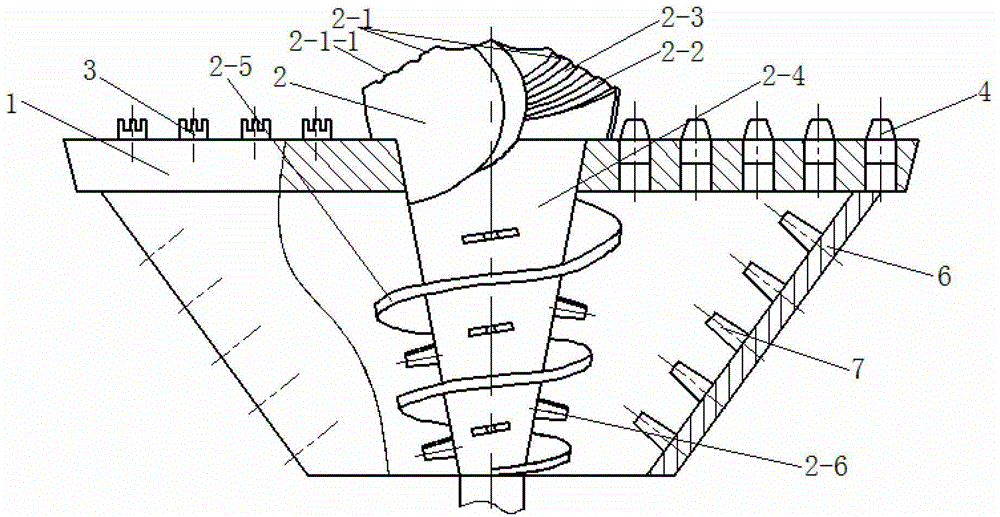
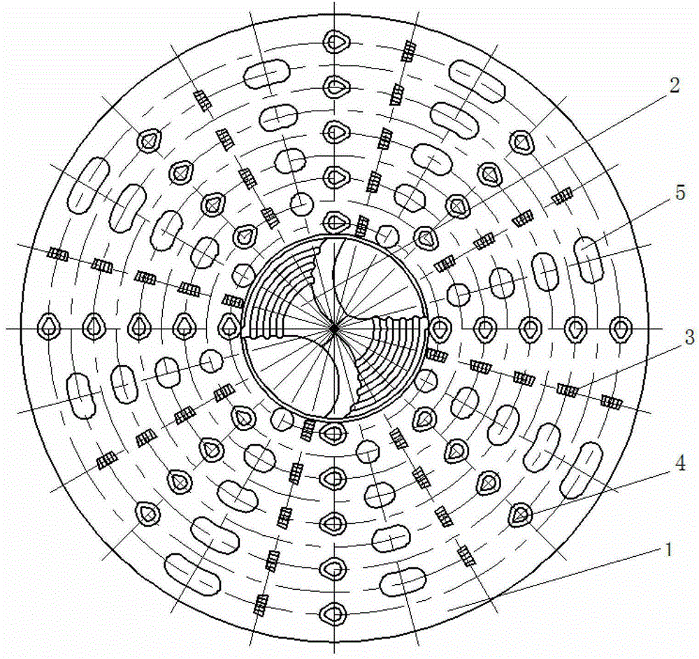
[0029] See figure 1 and figure 2 , a combined multi-stage debris drill bit in this embodiment includes an upper cutter head 1, a centering drill bit 2, 36 blades 3, 36 crushing teeth 4, 36 chip removal holes 5, a conical disc 6 and Five cutting teeth7.

[0030]The centering drill bit 2 is loaded into the tapered hole in the middle of the upper cutter head 1, and the contact circumference is welded. The two main edges 21 of the centering bit 2 are left-right symmetrical arc edges; Asymmetrically provided with a plurality of variable-pitch helical chipbreakers 2-3 on the connected flank 2-2; each main edge 2-1 of the centering drill bit 2 is composed of a plurality of short sections with a length not exceeding 30mm. Edge 2-1-1; chip breaker 2-3 is arranged between two sections of short edges 2-1-1, and the groove width of each chip breaker 2-3 is no more than 30mm. The centering drill bit 2 is located at the lower part of the upper cutter head 1 and is a cone rod 2-4, and th...

Embodiment 2)

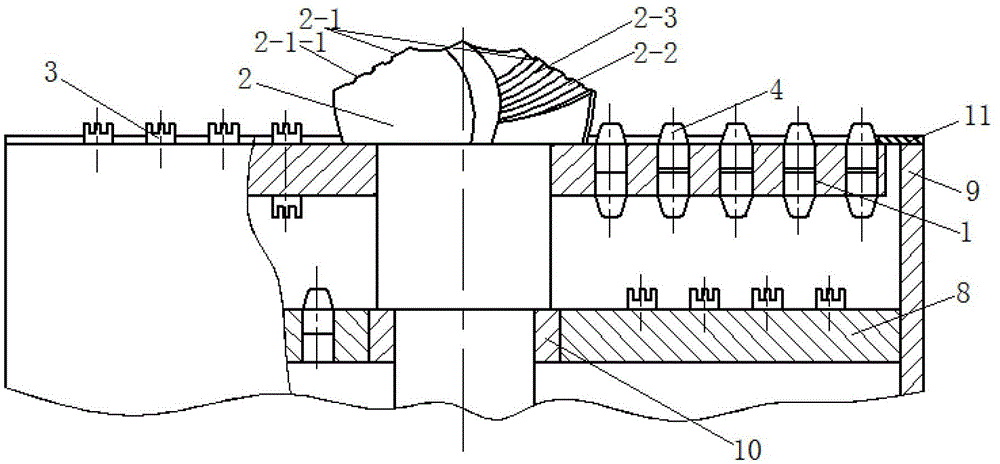
[0038] The difference between the combined multi-stage debris drill bit in this embodiment and the embodiment 1 lies in the secondary crushing chamber, which is composed of the lower cutter head 8 , the outer sleeve 9 and the upper cutter head 2 . A sliding bearing 10 is installed between the centering drill bit 2 and the lower cutter head 8; the inner hole of the sliding bearing 10 and the centering drill bit 2 are clearance fit, and the outer circle and the lower cutter head 8 are an interference connection. The upper cutterhead 1 and the lower cutterhead 8 are connected by an outer sleeve 9; the bottom surface of the upper cutterhead 1 is provided with 36 blades 3, 36 crushing teeth 4 and 36 corresponding to the upper surface of the upper cutterhead 1. Chip removal holes 5; the upper surface of the lower cutter head 8 is provided with 36 blades 3, 36 crushing teeth 4 and 36 chip removal holes 5 according to the same rule on the bottom surface of the upper cutter head 1, and ...


PUM


Abstract

The invention discloses a combined multistage mud chip crushing drill which comprises an upper cutter plate, a centering drill, a plurality of blades and a plurality of crushing teeth. The centering drill is welded in the middle portion of the upper cutter plate, two main blades of the centering drill are bilaterally symmetric arc blades; the plurality of blades and the plurality of crushing teeth are all arranged on the upper surface of the upper cutter plate; the tooth profile of each breaking tooth is axis-symmetric and forms a conical degree in the height direction, and one end is wider than the other. In the process of a trenchless drilling, the centering drill firstly contacts a gravel soil, and with a specific structure, can play a centering and guiding role and carry out cutting and chip removing on the middle portion of the gravel soil. The two tooth profiles have different functions and mutually affects the breaking function of rocks to enable the rock breaking to be more easier, so that the combined multistage mud chip crushing drill can provide the mud chips needed by the mud chip pneumatic conveying.

Description

technical field [0001] The invention relates to a facility for municipal road construction, in particular to a combined type debris-crushing drill bit. Background technique [0002] Trenchless technology refers to the construction technology of laying, repairing and replacing underground pipelines and cables without digging trenches on the ground. Because of its advantages such as fast construction speed, little interference to the ground, low overall cost, and good safety, it has been increasingly used in the construction of municipal roads in recent years. Although the trenchless pipeline construction technology and equipment at home and abroad have developed rapidly in recent years, the degree of functional automation is also getting higher and higher. However, most trenchless pipeline construction equipment occupies a large area, the equipment is expensive, and a high-pressure cement slurry system is used to discharge mud. This not only wastes water resources and energy...

Claims


Application Information

Patent Timeline
Patent Type & Authority Patents(China)
IPC IPC(8): E21B10/43
Inventor 刘海兰李小平
Owner CHANGZHOU COLLEGE OF INFORMATION TECH
Why Eureka
Try Eureka