Engine control device

A control device and engine technology, applied in the direction of engine control, combustion engine, machine/engine, etc., can solve problems such as torque shock, and achieve the effect of suppressing sudden change, improving convergence, and preventing long-term

Active Publication Date: 2013-04-17
MITSUBISHI MOTORS CORP
View PDF4 Cites 6 Cited by
  • Summary
  • Abstract
  • Description
  • Claims
  • Application Information

AI Technical Summary

Problems solved by technology

Especially immediately after the accelerator pedal is pressed to end the fuel cut control, the engine output power corresponding to the accelerator operation amount is required, and torque shock is likely to occur.

Method used


Image

  • Engine control device
  • Engine control device
  • Engine control device

Examples


Embodiment Construction

[0035] An engine control device will be described with reference to the drawings. In addition, the embodiment shown below is only an illustration, and it does not intend to exclude the application of various deformation|transformation and techniques which are not expressly shown in the following embodiment. The structures of this embodiment can be modified in various ways without departing from their gist, and can be selected or combined as needed.

[0036] [1. device structure]

[0037] [1-1. engine]

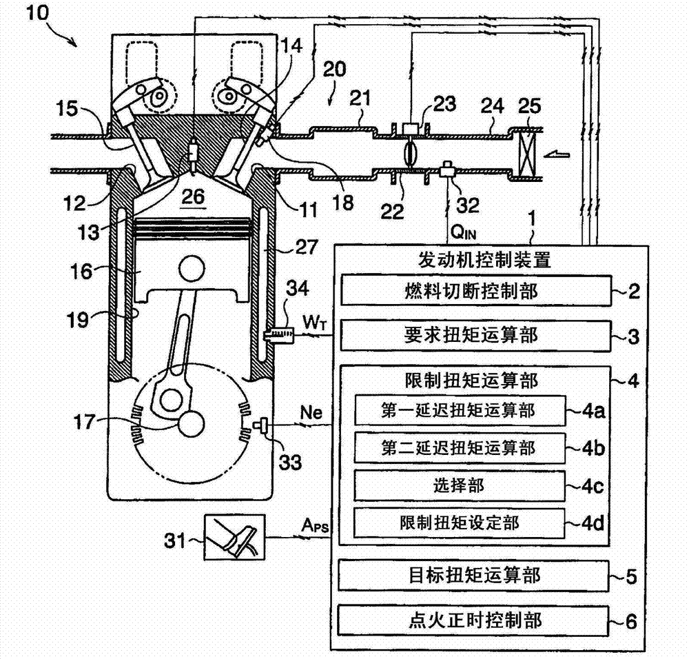
[0038] The engine control device of this embodiment is suitable for figure 1 An on-board gasoline engine 10 is shown. Here, one of the plurality of cylinders provided in the multi-cylinder engine 10 is shown. The piston 16 is attached so as to freely reciprocate and slide along the inner peripheral surface of a hollow cylindrical cylinder 19 . The space enclosed by the upper surface of the piston 16 and the inner peripheral surface and top surface of the cylinder 19 func...


PUM


Abstract

The invention refers to an engine control device which can restrain torque impact of an engine and meanwhile can raise a fuel consumption rate. The engine control device includes a required torque calculating unit (3) for calculating a required torque required by an engine (1), and a delay torque calculating unit (4) for calculating a delay torque which performs delay process on a required torque. In addition, the engine control device also includes an ignition control unit (6) for controlling an ignition timing of an engine (10) according to the delay torque. The delay torque calculating unit (4) uses a time constant with given response faster than air suction response delay of the engine (10).

Description

technical field [0001] The present invention relates to an engine control device that controls ignition timing upon return from a fuel cut state and a torque down state. Background technique [0002] Conventionally, a fuel cut control that temporarily cuts off fuel supply to an engine is known as one of controls aimed at improving vehicle fuel consumption and purifying exhaust gas. The fuel cut control refers to controlling the fuel injection amount at the time of deceleration of the vehicle to be zero or close to zero. The fuel cut control is executed, for example, when the accelerator pedal is not depressed and the engine is braked, that is, when the drive wheels are braked by rotational resistance of the engine. On the other hand, when the accelerator pedal is depressed and the engine speed drops to a lower speed range while the fuel cut control is in effect, the fuel cut control ends. At this time, the fuel supply to the engine is resumed, and the engine output corresp...

Claims


Application Information

Patent Timeline
Patent Type & Authority Applications(China)
IPC IPC(8): F02D43/00
CPCY02T10/40
Inventor 柴田晃史上田克则宫田敏行
Owner MITSUBISHI MOTORS CORP
Why Eureka
Try Eureka