Plunger lifting mechanism of rotary valve type diaphragm carburetor

A rotary valve type, carburetor technology, applied in the direction of machines/engines, etc.

Inactive Publication Date: 2013-04-17
ZHEJIANG RUIXING CARBURETOR MFG
View PDF5 Cites 3 Cited by
  • Summary
  • Abstract
  • Description
  • Claims
  • Application Information

AI Technical Summary

Problems solved by technology

[0007]Based on the above problems, the present invention provides a rotary valve type diaphragm carburetor plunger lifting mechanism, which aims to solve the problem that the cam is located outside the carburetor, and it is easy to Enter the dust and affect the flexibility of the carburetor, thereby affecting the normal operation of the engine

Method used


Image

  • Plunger lifting mechanism of rotary valve type diaphragm carburetor
  • Plunger lifting mechanism of rotary valve type diaphragm carburetor
  • Plunger lifting mechanism of rotary valve type diaphragm carburetor

Examples


Embodiment Construction

[0053] The following description is merely exemplary in nature and not intended to limit the disclosure, application or use. It should be understood that throughout the drawings, corresponding reference numerals indicate like or corresponding parts and features.

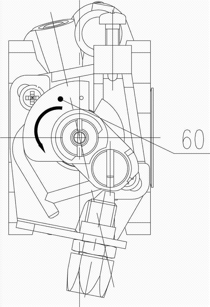
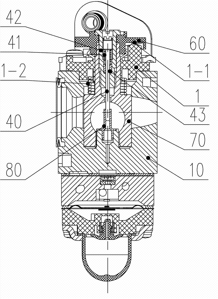
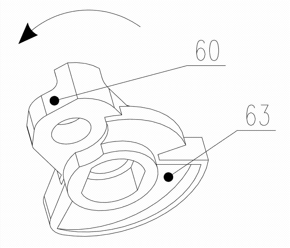
[0054] Referring now to the accompanying drawings, Figure 4 , Figure 5 , Image 6 , Figure 9 The outline structure diagram of the carburetor of the present invention is described. Carburetor has body 10, middle body 20, lower body 30, middle body 20 one side is equipped with oil return pipe 4 and oil inlet pipe 5, to obtain fuel from the fuel tank of engine, when engine stops working, by oil return pipe 4 The fuel in the oiler returns to the fuel tank of the engine; the bottom of the lower body 30 is equipped with an oil cup 3 . A limiting groove 13 is formed in an inner cavity (not marked) of the body 10 , and the limiting groove 13 is used for fixing the cam 60 . The top of the main body 10 is provided wit...


PUM


Abstract

The invention relates to a carburetor lifting mechanism, in particular to a plunger lifting mechanism of a rotary valve type diaphragm carburetor. The lifting mechanism comprises a torsion spring, a sealing cap, a cam, a plunger and a main nozzle. An oil return pipe and an oil inlet pipe are arranged in a middle section of the carburetor, and an oil cup is mounted at the bottom of a lower section of the carburetor. The plunger is disposed in the inner cavity of the body; and the cam is arranged in the inner cavity of the body through the limit groove. When in rotating of the throttle cable bracket on the top of the body, the wheel on the plunger is driven to roll along the helical surface on the cam, so that a major gauge pin in a major pin sleeve is driven to make up and down movements in the plunger. The cam is disposed in the inner cavity of the body, so that dust generated in the operation of the engine does not enter the cam to affect the normal work of the plunger, the reliability of the use of the carburetor is increased, and the proper engine work is guaranteed.

Description

technical field [0001] The invention relates to a carburetor lifting mechanism, in particular to a rotary valve type diaphragm carburetor plunger lifting mechanism. Background technique [0002] The carburetor is a mechanical device that mixes a certain proportion of gasoline with air under the vacuum generated by the engine. As a precise mechanical device, the carburetor can be called the "heart" of the engine for its important role in the engine. Its complete device should include starting device, idle speed device, medium load device, full load device and acceleration device. The carburetor will automatically mix the corresponding concentration according to the requirements of different working conditions of the engine, and output the corresponding amount of mixed gas. In order to make the mixed gas mixed evenly, the carburetor also has the effect of atomizing the fuel , for the normal operation of the machine. [0003] Existing carburetors such as Figure 1-Figure 3 s...

Claims


Application Information

Patent Timeline
Patent Type & Authority Applications(China)
IPC IPC(8): F02M7/14F02M7/18
Inventor 陈其安贾永成
Owner ZHEJIANG RUIXING CARBURETOR MFG
Why Eureka
Try Eureka