Hydraulic retarder

A hydraulic retarder and heat exchanger technology, applied in the direction of liquid resistance brakes, brake types, mechanical equipment, etc., can solve the problem of affecting the braking effect of the hydraulic retarder, slow sliding of the piston, and affecting the oil supply of the retarder To achieve the effect of improving heat exchange efficiency, increasing oil inlet speed and reducing reverse resistance

Inactive Publication Date: 2013-04-17
韦健全
View PDF3 Cites 21 Cited by
  • Summary
  • Abstract
  • Description
  • Claims
  • Application Information

AI Technical Summary

Problems solved by technology

Since the piston guide hole is filled with oil, the piston will compress the oil in the guide hole when it is working. When the oil is compressed, it will give the piston a reaction force, making the piston slide slowly and affecting the oil supply of the retarder. Therefore, it will affect the hydraulic retarder. brake effect

Method used


Image

  • Hydraulic retarder
  • Hydraulic retarder
  • Hydraulic retarder

Examples


Embodiment Construction

[0030] The present invention will be further described below in combination with specific embodiments.

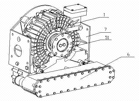
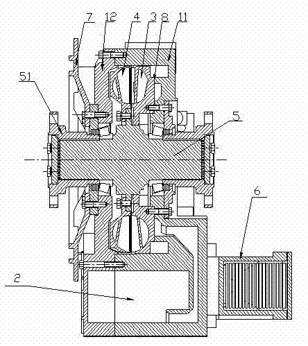
[0031] see figure 1 and figure 2 : The hydraulic retarder includes a hydraulic retarder housing 1, an oil storage tank 2, a stator 3, a rotor 4 and a heat exchanger 6, the stator 3 and the rotor 4 are installed in the working chamber, and the oil storage tank 2 and the working chamber are arranged in Inside the hydraulic retarder shell 1, the heat exchanger 6 is fixedly installed outside the shell. The stator 3 is connected to the hydraulic retarder housing 1 through bolts, and the rotor 4 is mounted on the spline shaft 5 through bolts and can rotate with the spline shaft 5 . On the stator 3 and along the circumferential direction of the stator 3, an oil inlet a33 and an oil outlet are provided. The oil inlet a33 of the stator 3 communicates with the oil storage tank 2 through the first oil inlet, and the oil outlet of the stator 3 passes through the oil outlet. The pas...


PUM


Abstract

The invention discloses a hydraulic retarder. The hydraulic retarder comprises a hydraulic retarder shell, an oil storage tank, a stator, a rotor and a heat exchanger, wherein the oil storage tank, the stator and the rotor are all arranged in the hydraulic retarder shell, and the heat exchanger is fixedly arranged outside the hydraulic retarder shell; oil inlet holes a and oil outlet holes are arranged on the stator and along the periphery of the stator; and a second oil inlet channel is internally provided with a check valve, the check valve comprises a piston, a spring, a piston guide hole and an oil discharge groove, one end of the piston is pressed at the end part of the heat exchanger shell to block an oil inlet, the other end of the piston extends into the piston guide hole to be matched with the piston guide hole in a sliding mode, the spring is sheathed on the piston, one end of the spring is pressed on the piston, the other end of the spring is pressed on the hydraulic retarder shell, and the piston guide hole is communicated with an oil outlet by the oil discharge groove. When oil in the piston guide hole is compressed by the piston, the oil is discharged by the oil discharge groove, so that the counter-acting force is not generated to the piston to block the movement of the piston, the oil feeding speed of the retarder is enhanced, and the response time of the retarder is improved.

Description

technical field [0001] The invention relates to the technical field of vehicle auxiliary braking, in particular to a hydraulic retarder with good braking performance. [0002] Background technique [0003] Automobile braking system is one of the most important systems in the safe driving of automobiles. With the development of engine technology and the improvement of road conditions, the driving speed and single running distance of the car have been greatly developed, and the driving kinetic energy has been greatly improved, which makes the traditional friction plate brake device more and more unable to adapt Long-term, high-intensity work needs. Due to the frequent or long-term use of the service brake, the phenomenon of thermal degradation of the brake performance due to overheating of the friction plate will occur, and in severe cases, the brake will fail, threatening the driving safety, and the vehicle will also increase the transportation cost due to frequent replacem...

Claims


Application Information

Patent Timeline
Patent Type & Authority Applications(China)
IPC IPC(8): F16D57/00
Inventor 韦健全徐显营
Owner 韦健全
Why Eureka
Try Eureka