Planar magnetron sputtering cathode

A magnetron sputtering, planar technology, applied in discharge tubes, electrical components, circuits, etc., can solve the problems of damage to coating equipment, uneven etching, and high coating costs, and achieve improved utilization, wider etching area, and magnetic field. The effect of uniform intensity distribution

Inactive Publication Date: 2013-04-17
HONG FU JIN PRECISION IND (SHENZHEN) CO LTD +1
View PDF5 Cites 5 Cited by
  • Summary
  • Abstract
  • Description
  • Claims
  • Application Information

AI Technical Summary

Problems solved by technology

When the etching pit 211 is deep enough, the target 201 needs to be replaced, otherwise the target 201 will be broken down and cause damage to the coating equipment
The uneven etching of the target 201 of the planar cathode makes the utilization rate of the target 201 low, usually only 20-30%, and the coating cost is high

Method used


Image

  • Planar magnetron sputtering cathode
  • Planar magnetron sputtering cathode
  • Planar magnetron sputtering cathode

Examples


Embodiment Construction

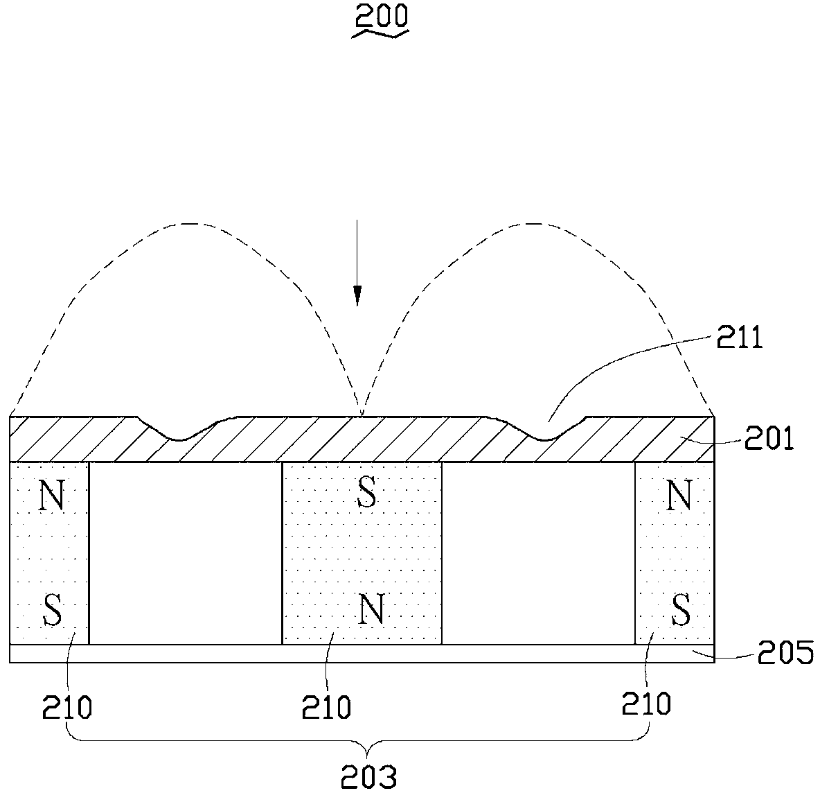
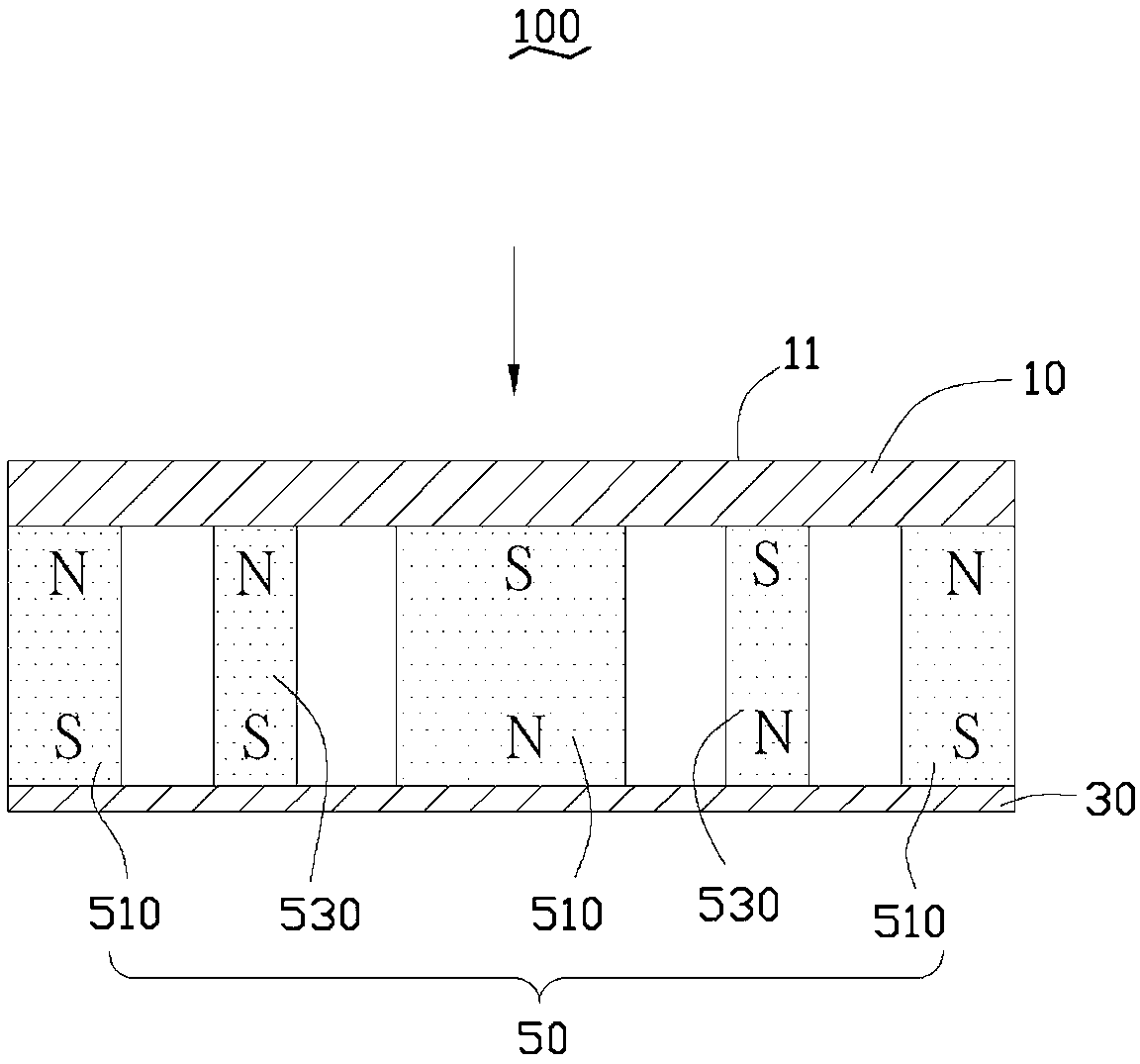
[0018] see image 3 , the planar magnetron sputtering cathode 100 of the present invention includes a target 10 , a magnet device 50 , and a magnetic shoe 30 . The target 10 is a planar target, which includes a sputtering surface 11 . The magnet device 50 is vertically installed on a side of the target 10 opposite to the sputtering surface 11 , and the magnetic shoe 30 is arranged on a side of the magnet device 50 away from the target 10 . The magnetic shoe 30 is used to shield the magnetic field of the side of the magnet device 50 adjacent to the magnetic shoe 30 .

[0019] The magnet device 50 includes three first magnets 510 and two second magnet groups 530 . The three first magnets 510 are arranged at equal intervals on both sides and in the middle of the target 10 , and the polarity arrangement of each adjacent two first magnets 510 is opposite.

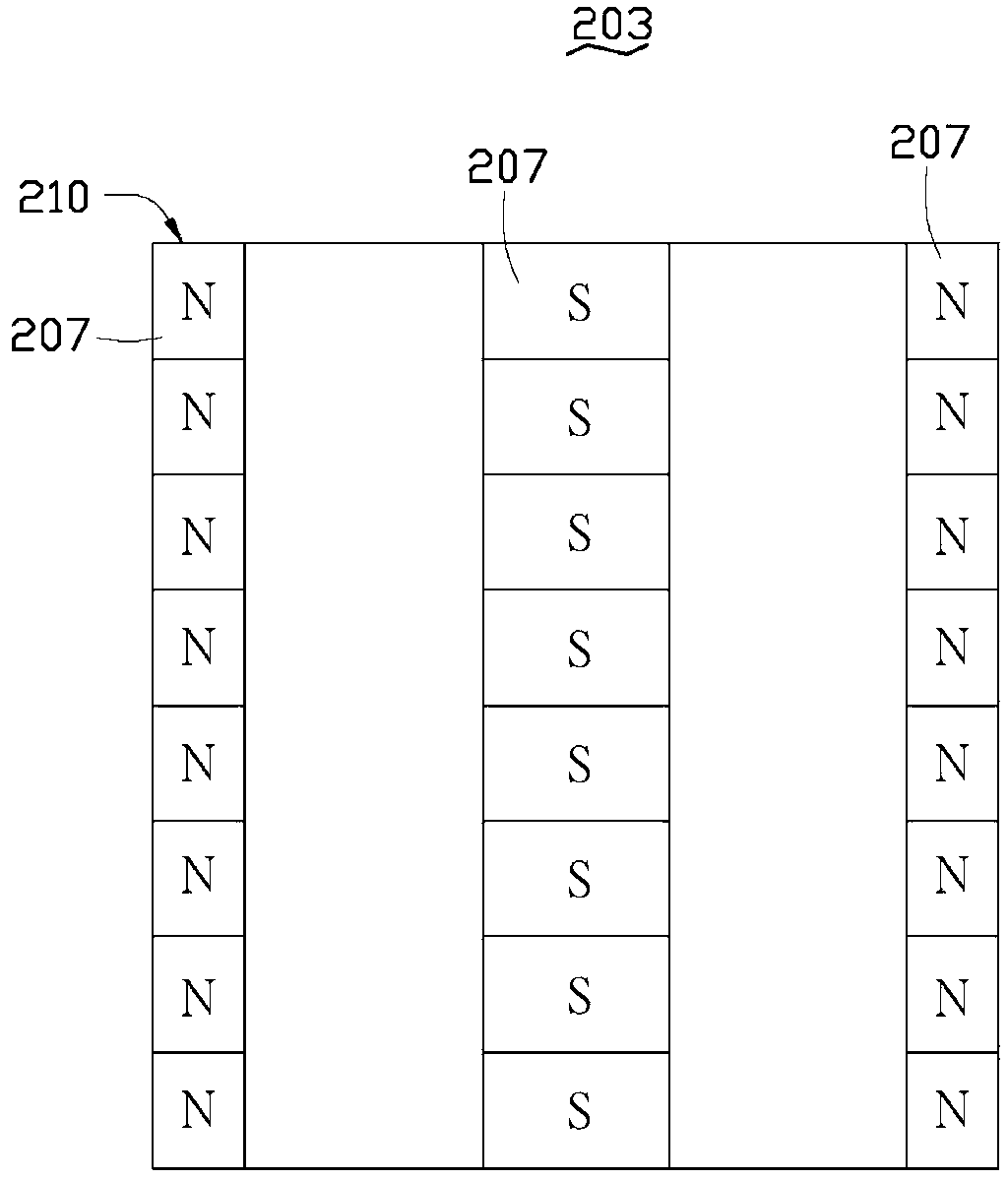
[0020] Please also refer to Figure 4 , Figure 4 shown as image 3 After removing the target 10, from image 3 The mag...


PUM


Abstract

The invention discloses a planar magnetron sputtering cathode which comprises a target material, a magnet device and a magnet shoe, wherein the magnetic device is arranged on one surface, which is opposite to a sputtering surface, of the target material, the magnet shoe is arranged on one surface, which is far away from the target material, of the magnet device, the magnet device comprises three first magnets which are arranged in parallel at uniform intervals and are respectively positioned on two sides and the middle of the target material, polarities of the two adjacent first magnets are opposite, the magnet device also comprises two second magnet groups, each second magnet group is arranged between two adjacent first magnets, each second magnet group comprises a plurality of second magnets arranged longitudinally at uniform intervals, and polarities of two adjacent second magnets in each second magnet group are opposite. According to the planar magnetron sputtering cathode, the magnetic field strength on the surface of the target material is more uniformly distributed to ensure that the etching region on the surface of the target material is greatly widened, and thus the utilization rate of the target material is effectively utilized.

Description

technical field [0001] The invention relates to a planar magnetron sputtering cathode, in particular to a planar magnetron sputtering cathode capable of improving target material utilization. Background technique [0002] Physical vapor deposition (Physical Vapor Deposition, referred to as PVD) is a technology that uses physical methods to deposit thin films on substrates. Magnetron sputtering technology is a kind of physical vapor deposition technology. In the magnetron sputtering coating technology, high-energy ions (usually argon ions accelerated by an electric field) bombard the surface of the target, and the ions or atoms on the target surface exchange energy with the incident high-energy ions. film deposited on the material. [0003] At present, planar magnetron sputtering cathodes are widely used in the application field of magnetron sputtering coating technology. like figure 1 The shown existing planar magnetron sputtering cathode 200 includes a target 201 , a ma...

Claims


Application Information

Patent Timeline
Patent Type & Authority Applications(China)
IPC IPC(8): H01J37/04H01J37/34
Inventor 黄登聪彭立全
Owner HONG FU JIN PRECISION IND (SHENZHEN) CO LTD
Why Eureka
Try Eureka