Methods for reducing path loss while testing wireless electronic devices with multiple antennas

A path loss and equipment technology, applied in transmission monitoring, instruments, wireless communication, etc., can solve problems such as the second antenna is not correct, the first antenna is not correct, etc.

Active Publication Date: 2013-04-17
APPLE INC
View PDF3 Cites 9 Cited by
  • Summary
  • Abstract
  • Description
  • Claims
  • Application Information

AI Technical Summary

Problems solved by technology

If, in this fixed position, the first antenna is placed closer to the test antenna, the measurement results may be biased towards the first antenna (i.e. the test results may be more correct for the first antenna, but less correct for the second antenna)

Method used


Image

  • Methods for reducing path loss while testing wireless electronic devices with multiple antennas
  • Methods for reducing path loss while testing wireless electronic devices with multiple antennas
  • Methods for reducing path loss while testing wireless electronic devices with multiple antennas

Examples


Embodiment Construction

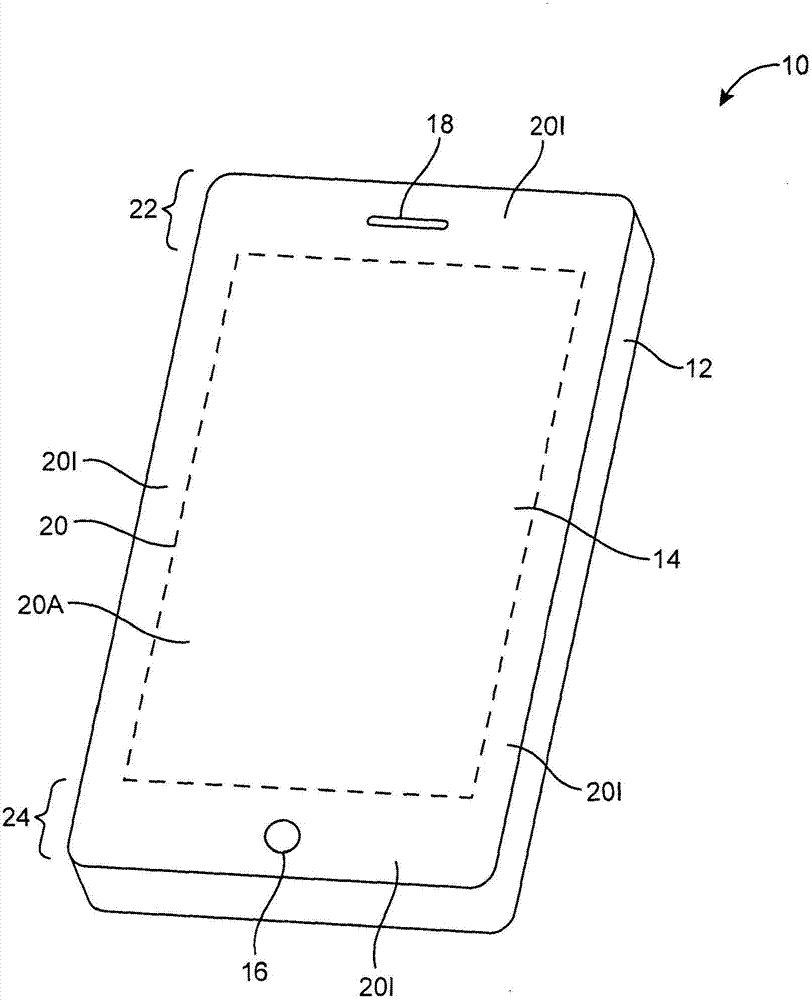
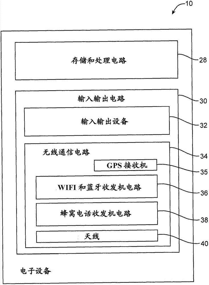
[0021] Electronic devices may be provided with wireless communication circuitry. Wireless communication circuitry may be used to support wireless communication in multiple wireless communication frequency bands. The wireless communication circuitry may include multiple antennas arranged to implement an antenna diversity system.

[0022] Antennas may include loop antennas, inverted-F antennas, strip antennas, planar inverted-F antennas, slot antennas, hybrid antennas including more than one type of antenna structure, or other suitable antennas. The conductive structure of the antenna may be formed by conductive electronic device structures, such as conductive housing structures, traces on a substrate such as traces on a plastic, glass or ceramic substrate, traces on a flexible printed circuit board ("flex circuit") traces, traces on a rigid printed circuit board such as a fiberglass-filled epoxy board), sections of patterned metal foil, wires, conductor strips, other conductiv...


PUM


Abstract

A test station may include a test host, a test unit, and a test enclosure. A device under test (DUT) having at least first and second antennas may be placed in the test enclosure during production testing. Radio- frequency test signals may be conveyed from the test unit to the DUT using a test antenna in the test enclosure. In a first time period during which the performance of the first antenna is being tested, the DUT may be oriented in a first position such that path loss between the first antenna and the test antenna is minimized. In a second time period during which the performance of the second antenna is being tested, the DUT may be oriented in a second position such that path loss between the second antenna and the test antenna is minimized. The DUT is marked as a passing DUT if gathered test data is satisfactory.

Description

Background technique [0001] The present application relates generally to testing electronic devices, and more particularly, to testing electronic devices that include multiple antennas. [0002] Electronic devices often contain wireless communication circuitry. For example, a device can use 2.4GHz and 5.0GHz (IEEE 802.11) frequency band for communication. Wireless communication is also possible in cellular telephone telecommunications bands and other radio frequency bands. In schemes such as antenna diversity schemes, electronic devices may use arrays with multiple antennas to handle wireless communications. [0003] When multiple antenna wireless devices of this type are manufactured in high volumes, an RF test station can be used to evaluate the performance of the wireless communication circuitry on each device to ensure that each device meets design guidelines. An RF test station typically includes a test mainframe, a tester (eg, a signal generator), and an electromagn...

Claims


Application Information

Patent Timeline
IPC IPC(8): H04B17/00
CPCG01R29/0821H04W24/06G01R29/10
Inventor J·G·尼科尔M·帕斯科林尼申志一
Owner APPLE INC
Why Eureka
Try Eureka