
Test station for wireless devices and methods for calibration thereof

a wireless device and wireless technology, applied in the direction of receiving monitoring, measuring devices, instruments, etc., can solve the problems of high level of effort, time and money, and limited use of dut type-specific test stations, and achieve rapid complex testing for mimo duts having multiple inputs/outputs

Active Publication Date: 2013-07-25
ETHER CAPITAL CORP
View PDF2 Cites 31 Cited by
  • Summary
  • Abstract
  • Description
  • Claims
  • Application Information

AI Technical Summary

Benefits of technology

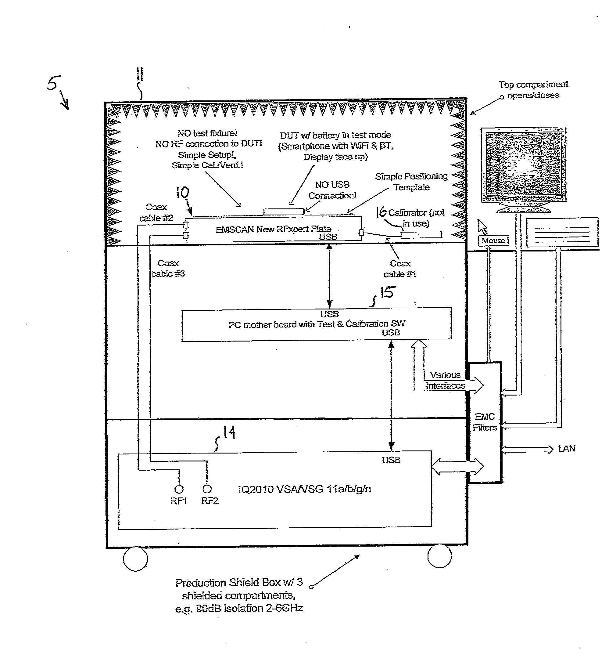
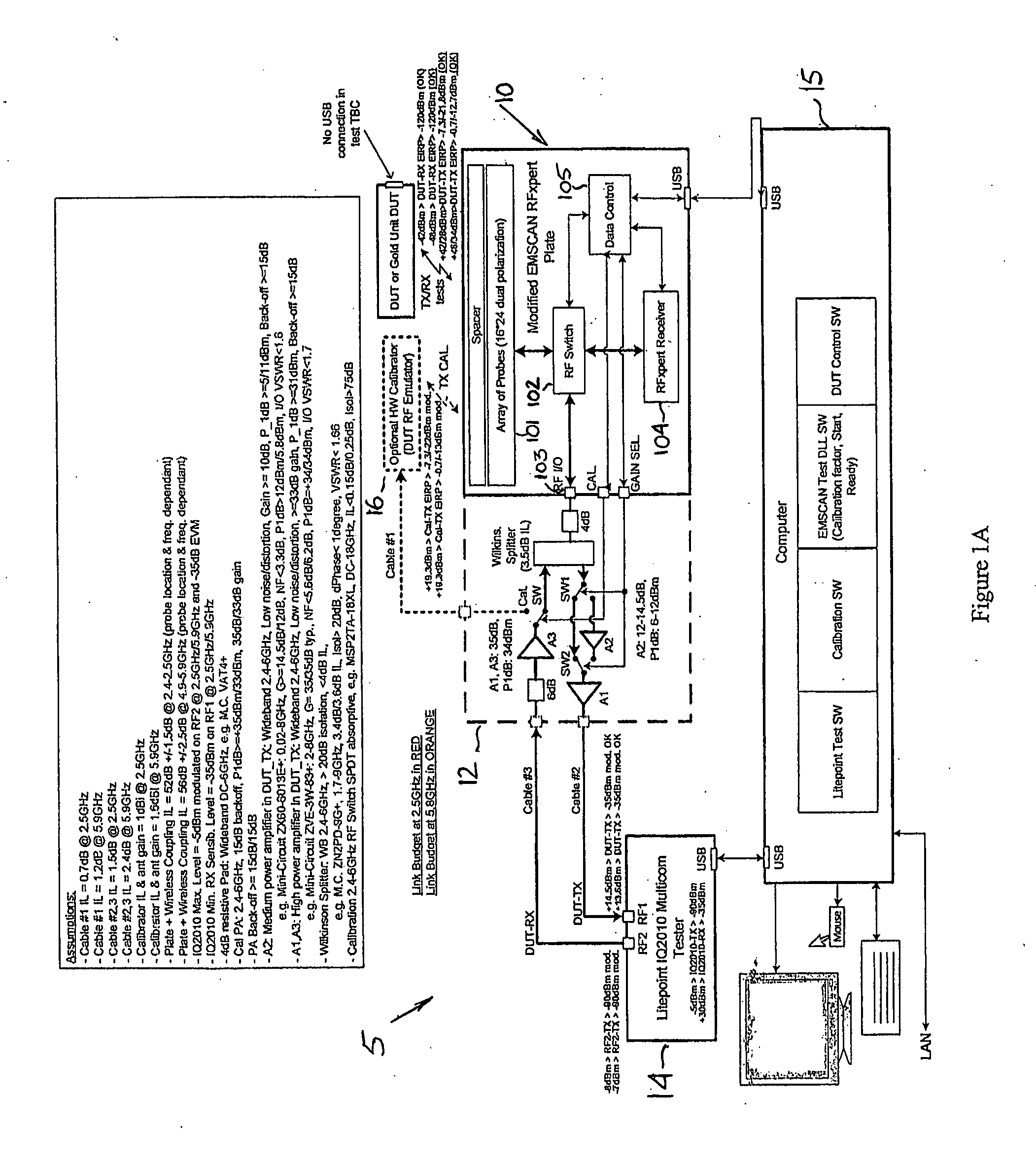
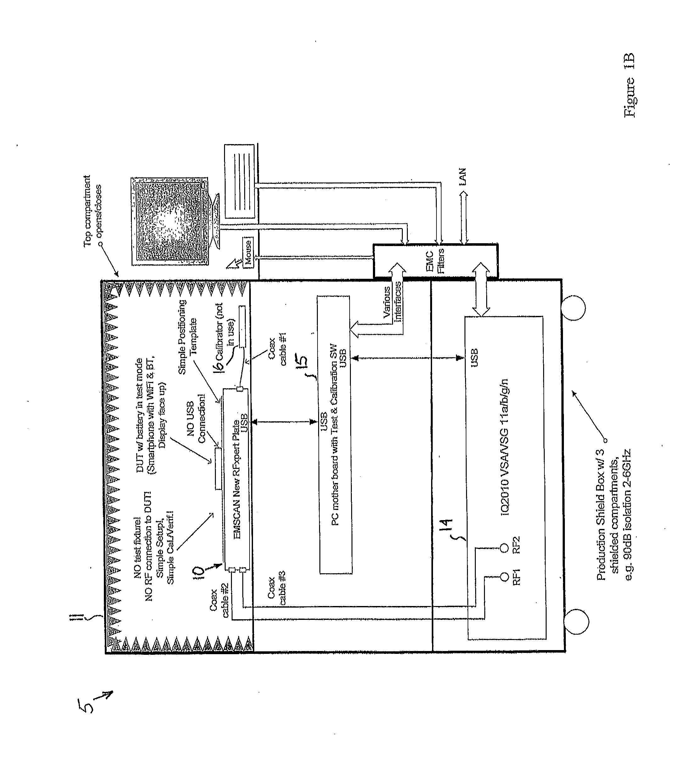
The present invention provides a method and apparatus for calibrating a test station for testing a wireless device in transmit mode. The test station includes a signal generator, a calibrator with a calibrator antenna, a receiving antenna, a signal analyzer, and a computer. The method involves using the signal generator to generate a calibration signal, transmitting the calibration signal through the calibrator antenna and receiving it at the signal analyzer, measuring the power level of the calibration signal, and correlating it to the target power level and bit error rate. The apparatus includes a variably controllable generator amplifier or attenuator for adjusting the amplitude of the calibration signal, a variably controllable analyzer amplifier or attenuator for setting the amplitude of the calibration signal, and a bit error detector for measuring the bit error rate of the calibration signal. The technical effect of the invention is to provide a more accurate and reliable method for calibrating a test station for testing wireless devices in transmit mode.

Problems solved by technology

The need for physical connections between the test station and the DUT or GU typically requires the fixtures and probes of conventional testing stations to be specifically designed for, and therefore limited to use, with a particular DUT type (e.g. a specific make and model of cellular phone) or GU.
Accordingly, a high level of effort, time and money is required to create DUT type-specific test stations and to reconfigure test stations for different DUT types.
Testing rapidly becomes complex for MIMO DUTs having multiple inputs / multiple outputs.
Physically connecting and disconnecting the DUT or the GU creates wear and tear on both the test station and the DUT or GU.
Finally, it is difficult to create many GUs and maintain them to the level of desired performance.
It is particularly difficult to create and maintain “just good enough” or “just bad enough” GUs to verify calibration at marginal pass or marginal fail limits, respectively.

Method used


Image

  • Test station for wireless devices and methods for calibration thereof
  • Test station for wireless devices and methods for calibration thereof
  • Test station for wireless devices and methods for calibration thereof

Examples


Embodiment Construction

[0060]The invention relates to a system and method for calibrating a test station for wireless devices. When describing the present invention, all terms not defined herein have their common art-recognized meanings. To the extent that the following description is of a specific embodiment or a particular use of the invention, it is intended to be illustrative only, and not limiting of the claimed invention. The following description is intended to cover all alternatives, modifications and equivalents that are included in the spirit and scope of the invention, as defined in the appended claims.

[0061]As used herein, a “wireless device” means any device which transmits, receives or both transmits and receives signals in the form of electromagnetic radiation (irrespective of power or range). Wireless devices may use configurations or protocols such as, but not limited to, cellular telephony, WiFi, WiMax, Bluetooth, Zigbee, or the like. In one embodiment, the wireless device comprises a ce...


PUM


Abstract

A test station for wireless devices and methods for calibration thereof. The test station includes a signal generator, a calibrator, a scanner having receiving and transmitting antennas, a signal analyzer, and a computer. Under the direction of the computer, the signal generator generates a calibration signal in accordance with a programmable calibration signal script. The calibrator may be used to emulate either a wireless device in transmit mode by transmitting the calibration signal to the scanner for analysis by the signal analyzer, or a wireless device in receive mode by receiving the calibration signal from the scanner for analysis by the signal analyzer. The behavior of the test station is calibrated by correlating signal parameters of the calibration signal as specified by the calibration signal script and as measured at the signal analyzer.

Description

FIELD OF THE INVENTION[0001]The present invention is directed to a test station for wireless devices and methods for calibration thereof.BACKGROUND[0002]In the manufacturing process of wireless devices (e.g. cellular phones) that transmit and / or receive radio frequency (RF) signals, the wireless devices are tested at designated testing stations on the production line to ensure that the devices meet performance parameters regarding their transmit or receive functions. Conventional testing stations for wireless devices have fixtures configured to hold the device-under-test (DUT) in a specific position during testing, while probes make one or more conducted (wired) physical connection to the DUT. Passing devices are accepted and proceed to assembly and failing devices are rejected and repaired. Marginal units may be retested once or twice to confirm whether or not they pass. For maximum efficiency and profitability of the manufacturing process, the testing ideally consumes as little ti...

Claims


Application Information

Patent Timeline
Patent Type & Authority Applications(United States)
IPC IPC(8): G01R35/00
CPCG01R35/005H04B17/21H04B17/11
Inventor RADA, PATRICKPATTON, RUSKA
Owner ETHER CAPITAL CORP
Learn More