Automotive radar alignment

a technology for automotive radars and alignment methods, applied in the field of automotive radar alignment methods and systems, can solve problems such as errors in methods, and achieve the effects of improving signal-to-noise ratio, higher radar cross section, and greater mounting tolerances of radar sensing units

Active Publication Date: 2017-07-27
ROBERT BOSCH CORP +1
View PDF5 Cites 32 Cited by
  • Summary
  • Abstract
  • Description
  • Claims
  • Application Information

AI Technical Summary

Benefits of technology

[0005]The invention takes care to combine advantages of mirror and corner reflectors. A better signal to noise ratio results from higher radar cross section independent of a mounting position of the radar sensor unit. By providing the plural reflectors different distances from the vehicle and the radar sensor unit located at a test station, interference between reflected radar waves of the plural reflectors is minimized during calibration. The invention is especially useful for a radar sensor unit that is integrated behind a vehicle bumper and thus disposed out of view. Further, alignment of radar sensor units is performed with at least three corner reflectors, even if the radar sensor units are mounted at different heights or at different lateral positions on a vehicle that are not known.

Problems solved by technology

Thus, the method is error pro

Method used


Image

  • Automotive radar alignment
  • Automotive radar alignment
  • Automotive radar alignment

Examples


Embodiment Construction

[0026]Before any embodiments of the invention are explained in detail, it is to be understood that the invention is not limited in its application to the details of construction and the arrangement of components set forth in the following description or illustrated in the following drawings. The invention is capable of other embodiments and of being practiced or of being carried out in various ways.

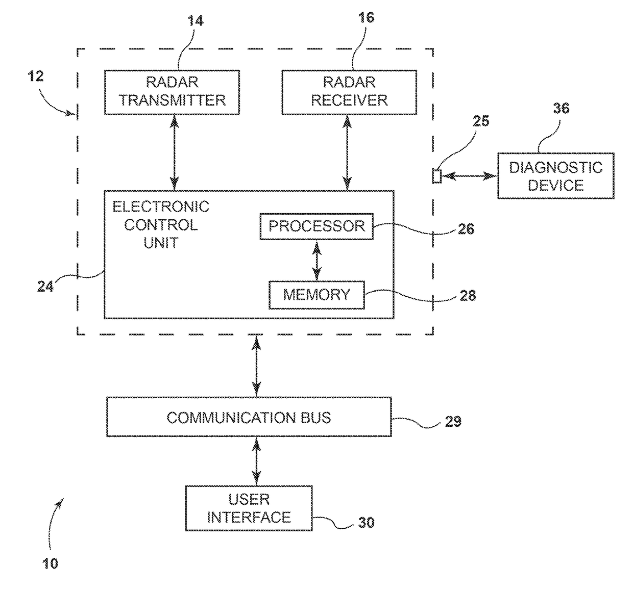
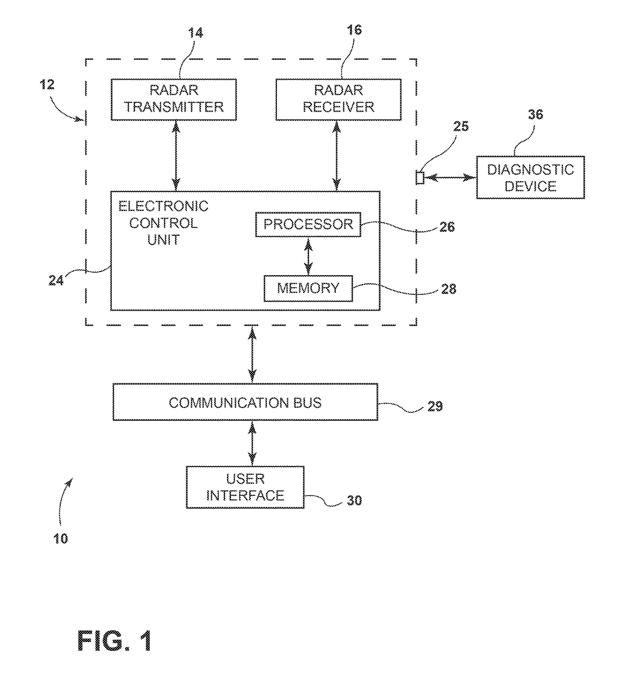
[0027]FIG. 1 shows a vehicle radar sensor system 10 that includes a radar sensor unit 12 having a radar transmitter 14 for transmitting a radar wave and a radar receiver 16 for receiving a reflected radar wave. The radar sensor unit 12 includes an electronic control unit (ECU) 24 connected to the radar transmitter 14 and the radar receiver 16. In one embodiment, the ECU 24 of the radar sensor unit 12 includes a diagnostic port 25.

[0028]In some constructions, the ECU 24 shown in FIG. 1 includes a processor 26 that has an executable alignment program stored in a non-transitory computer read...


PUM


Abstract

A method and apparatus for determining misalignment of a radar sensor unit mounted to a vehicle includes providing targets on an alignment apparatus. A vehicle is located at predetermined location on a test station an exact given distance from the alignment apparatus. The actual locations and distances of the targets from each other and from radar sensor unit of the vehicle at the test station are known and pre-stored. At least one target is a greater distance from the vehicle than the other targets. The targets receive and return a radar wave from the radar sensor unit. The radar sensor unit determines locations and distances of the targets and compares with the given or actual locations and distances of the targets to determine misalignment of the radar sensor unit. A calibration program automatically calibrates azimuth and elevation to adjust for misalignment.

Description

RELATED APPLICATIONS[0001]This application claims priority from U.S. provisional application 62 / 037,871, filed Aug. 15, 2014, the entire content of which is hereby incorporated by reference.BACKGROUND[0002]This invention relates to an automotive radar alignment method and system.[0003]There are two common methods to align automotive or vehicle radar units in an original equipment manufacturer plant. First is a passive alignment on an optical base. Second is an active alignment method, wherein the radar proves if it is in alignment. For the second method, one target is used, namely a corner reflector. For this approach, mounting tolerances of the radar sensor unit and the mirror directly influence the result of the measurement.[0004]Another method includes a mirror with three tilt angles that are provided in sequence. These three angle positions are used to determine the vertical misalignment angle of the radar. Therefore, three separate measurements are needed. Further, the radar se...

Claims


Application Information

Patent Timeline
IPC IPC(8): G01S7/40G01S13/93G01S13/931
CPCG01S7/4026G01S13/931G01S2013/9389G01S2007/4034G01S2007/403G01S7/4052G01S2013/93271G01S2013/93275G01S7/4034G01S7/403G01S7/4086G01S7/4095
Inventor HELLINGER, RAPHAELSCHWINDT, OLIVER F.
Owner ROBERT BOSCH CORP
Why Eureka
Try Eureka