
Underframe structure for a motor vehicle

A bottom structure and motor vehicle technology, applied in substructure, superstructure, subassembly of superstructure, etc., can solve problems such as complex costs

Inactive Publication Date: 2013-04-17
AUDI AG
View PDF5 Cites 2 Cited by
  • Summary
  • Abstract
  • Description
  • Claims
  • Application Information

AI Technical Summary

Problems solved by technology

[0004] However, a disadvantage of this generally known construction is that in order to ensure the protection of the component there must in any case be present on the extent occupied by the component in the transverse direction of the vehicle a crossbeam located in front of or below the component
Such structures are generally only obtainable by complex and cost-intensive means

Method used


Image

  • Underframe structure for a motor vehicle
  • Underframe structure for a motor vehicle
  • Underframe structure for a motor vehicle

Examples


Embodiment Construction

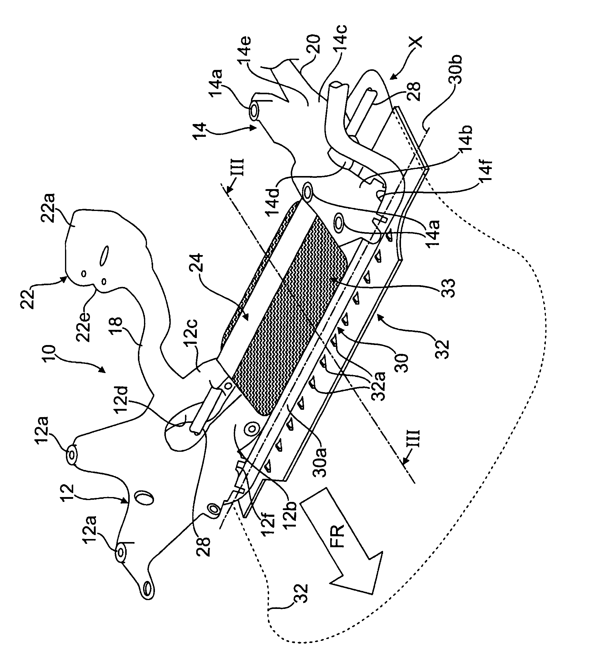
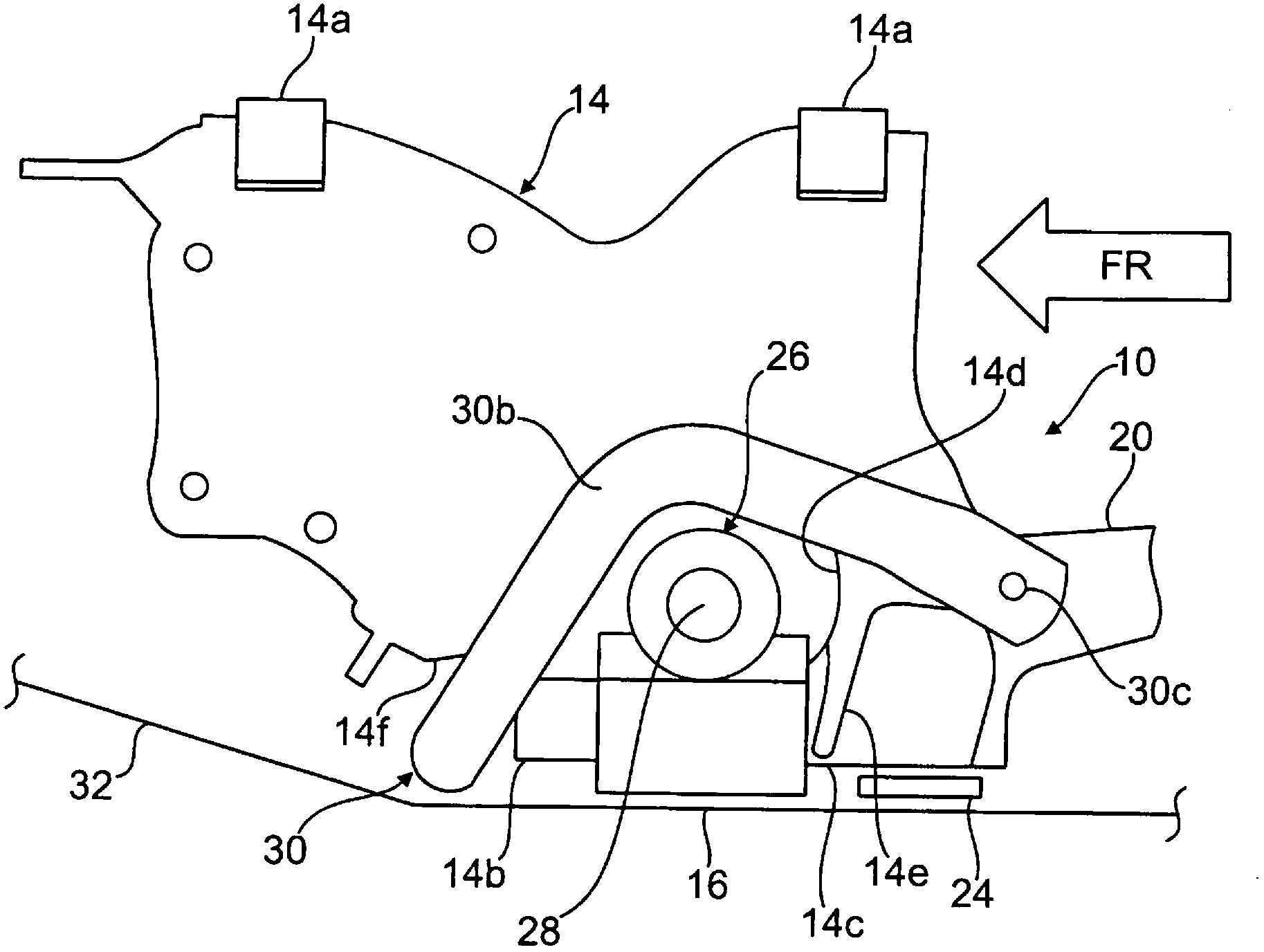
[0023] figure 1 "10" in the middle indicates the auxiliary frame 10 used for the front bottom structure of the motor vehicle. Rearwardly directed longitudinal, in particular pipe sections 18 , 20 and finally also plate-shaped lower cross braces 24 as cross beams reinforcing the sub-frame 10 , which is here designed in a U-shape, consist of the pipe sections 18 , 20 With formed functional nodules, especially casting nodules 22 (in figure 1 Only the casting nodule 22 on the right can be seen in , the casting nodule on the left is identically implemented in a mirror image).

[0024] The frame guide heads 12 , 14 and the end-side cast nodes 22 have fastening flanges 12 a , 14 a , 22 a via which the subframe 10 is bolted to a longitudinal member (not shown) of the body of the motor vehicle.

[0025] For example, the downwardly and inwardly projecting support arms 12b, 12c and 14b, 14c are firmly bolted to the cross brace 24 by means of fixing bolts (not shown), said support arms ...


PUM


Abstract

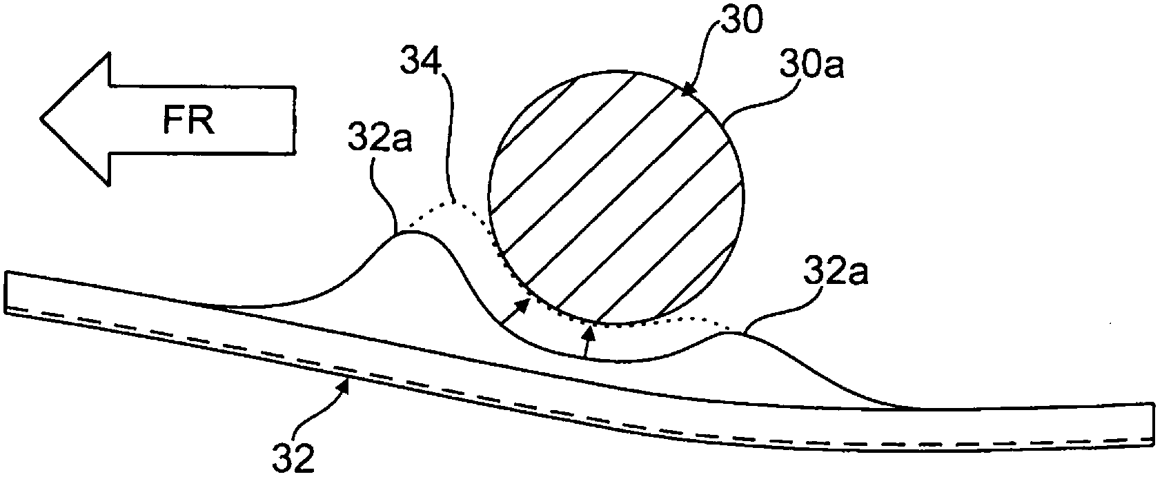
The invention relates to an underframe structure for a vehicle, in particular for a motor vehicle, having at least one assembly or component which is to be protected and which is arranged in the region of the underframe structure which preferably has a crossmember which reinforces said underframe structure, and having a stabilizer. According to the invention, a centre region (30a), running in the lateral direction of the vehicle, of the stabilizer (30) is positioned so far in the downward direction when viewed in the direction of the vertical axis of the vehicle that said centre region (30a) forms, independently of a crossmember arrangement of the underframe structure, both in the design position and in the state of spring compression, a rear end collision protection for assemblies (26) or components which are to be protected and which are arranged therebehind when viewed in the direction of travel or the longitudinal direction of the vehicle.

Description

technical field [0001] The invention relates to an underbody structure for a vehicle, in particular for a motor vehicle, according to the preamble of claim 1 . Background technique [0002] In modern vehicle construction, design requirements or packaging requirements, for example, often require extremely low installation positions for components. As a rule, therefore, the components which are located on or in the assembly which are the lowest in relation to the vehicle height axis and are most in need of protection due to their structure and function – such as the oil pan and the suction for the oil circuit behind the oil pan Devices or steering gears (just to give a few examples for the sake of illustration) - getting closer and closer to the bottom line preset for each vehicle and which must be complied with. [0003] The front axle structure usually has a cross member, the solid support of which is structurally designed in such a way that it is located either below and / o...

Claims


Application Information

Patent Timeline
IPC IPC(8): B60G21/055B60G7/02B62D21/11B62D25/20
CPCB60G21/055B60G7/02B60G2202/135B60G2204/1222B60G2204/15B60G2204/4308B62D21/11B62D21/155B62D25/082
Inventor S·鲁吉斯T·克莱默
Owner AUDI AG
Learn More