Overflow-discharge-type magnetic hydrocyclone
A technology of hydrocyclone and magnetic force, which is applied in the direction of swirling devices and devices whose axial direction can be reversed, can solve the problems of adverse effects of sorting operations, small effective magnetic field range, and reduced classification efficiency, etc., to achieve Low cost, large magnetic field range, and the effect of improving classification efficiency
- Summary
- Abstract
- Description
- Claims
- Application Information
AI Technical Summary
Problems solved by technology
Method used
Image
Examples
Embodiment 1
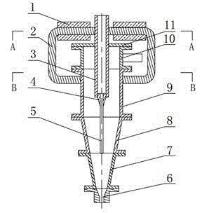
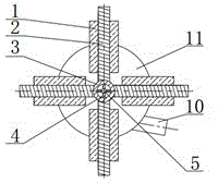
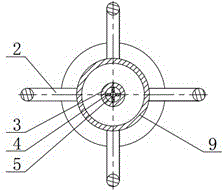
[0026] An overflow discharge type magnetic hydrocyclone. Such as figure 1 As shown, the overflow discharge type magnetic hydrocyclone includes an ordinary hydrocyclone, four U-shaped iron cores 2 wound with coils 1 and a central magnetically conductive rod 5 .
[0027] The ordinary hydrocyclone consists of a top cover 11, an ore feeding section 10, a cylinder 9, an upper cone 8, a lower cone 7, an overflow pipe 3 and a grit nozzle 6. The top cover 11 and the upper end of the ore feeding section 10, the lower end of the ore feeding section 10 and the upper end of the cylinder 9, the lower end of the cylinder 9 and the upper end of the upper cone 8, the lower end of the upper cone 8 and the upper end of the lower cone 7 And the lower end of the lower cone 7 and the housing of the grit chamber 6 are concentrically connected by flanges respectively.
[0028] The overflow pipe 3 is fixedly connected with the central hole of the top cover 11 , and the lower end of the overflow pip...
Embodiment 2
[0034] An overflow discharge type magnetic hydrocyclone. Except following technical parameter, all the other are with embodiment 1.
[0035] The overflow pipe 3 is fixedly connected with the central hole of the top cover 11 , and the lower end of the overflow pipe 3 is located at the bottom of the cylinder 9 . Such as figure 1 and Figure 4 As shown, the upper end of the central magnetic rod 5 is concentrically welded to the port at the lower end of the overflow pipe 3 through 2 to 3 connecting fins 4, the lower end of the central magnetic rod 5 is flush with the lower end of the upper cone 8, and the center The diameter of the magnetic rod 5 is 0.25-0.30 times the inner diameter of the overflow pipe 3 .
[0036] In this specific embodiment, one end of four U-shaped iron cores 2 wound with coil 1 is respectively welded on the outer wall of the upper part of overflow pipe 3 , and the other ends of four iron cores 2 are respectively welded on the outer wall of cylinder 9 . W...
PUM
 Abstract
Description
Claims
Application Information
 - R&D
- Intellectual Property
- Life Sciences
- Materials
- Tech Scout
- Unparalleled Data Quality
- Higher Quality Content
- 60% Fewer Hallucinations
Browse by: Latest US Patents, China's latest patents, Technical Efficacy Thesaurus, Application Domain, Technology Topic, Popular Technical Reports.
© 2025 PatSnap. All rights reserved.Legal|Privacy policy|Modern Slavery Act Transparency Statement|Sitemap|About US| Contact US: help@patsnap.com


