Laser cutter standalone automatic feeding and discharging device and laser cutter standalone automatic feeding and discharging method

A laser cutting machine, automatic loading and unloading technology, applied in the direction of laser welding equipment, welding equipment, metal processing equipment, etc., can solve the problems of increasing the labor burden of the operator, affecting the production efficiency of the cutting machine, inconvenience, etc., to reduce the operator The effect of burden, simple structure, and easy operation

Active Publication Date: 2013-04-24
SHENZHEN HANS MP LASER TECH CO LTD
View PDF6 Cites 72 Cited by
  • Summary
  • Abstract
  • Description
  • Claims
  • Application Information

AI Technical Summary

Problems solved by technology

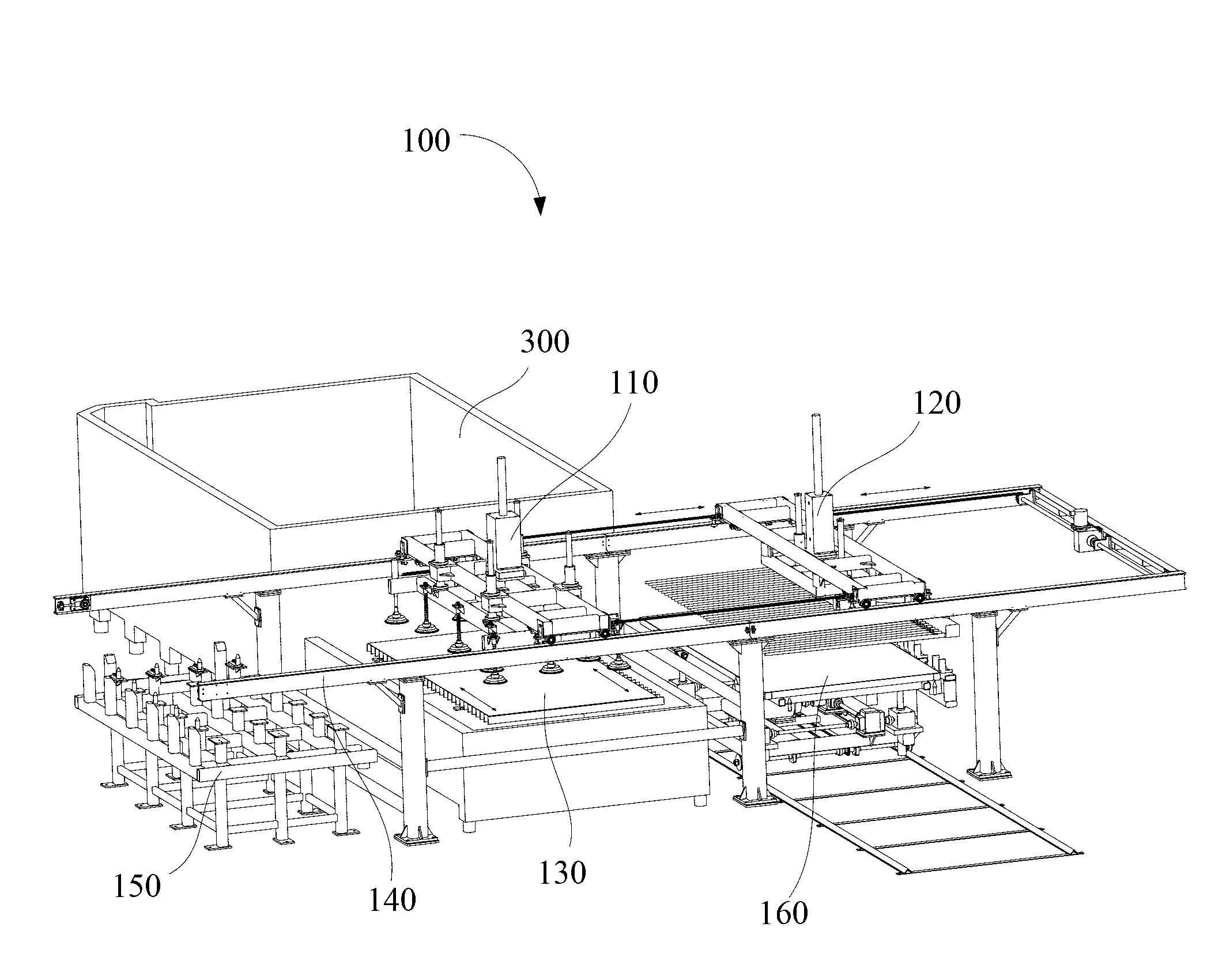
[0002] During the use of the traditional laser cutting machine, the operator needs to place the cutting workpiece to be processed by the laser cutting machine on the designated position of the laser cutting machine workbench, and then the laser cutting machine workbench automatically transports the cut workpiece to be processed to the cutting machine Laser processing is carried out in the processing area. After the cutting workpiece is processed (the cutting workpiece is processed into a part), the laser cutting machine table will be transported out of the processing area (this is the automatic operation step of the laser cutting machine), and then the operator needs to put The workpiece is placed from the laser cutting machine table to the designated position on the ground. Most of these two tasks are manually operated, and several people lift the board to the laser cutting machine table. This is called loading (putting the cut workpiece to be processed on The specified position on the cutting machine workbench is called loading), and the operator also needs to transfer the workpiece processed by the laser cutting machine worktable to other devices on the ground, which is called unloading (the workpiece processed by the laser cutting machine is transferred from The transfer of the laser cutting machine workbench to other devices on the ground is called unloading). The two tasks of loading and unloading are basically manual operations, and they are carried by several people (the range of normal cutting workpieces: the size of the cutting workpiece is 3 meters* 1.5 meters, the thickness is 1-16mm, and the weight is 36kg-576kg), which not only affects the production efficiency of the cutting machine, but also increases the labor burden of the operator. Some laser cutting machines use a simple suction device, which is basically manual operation, which is very inconvenient

Method used


Image

  • Laser cutter standalone automatic feeding and discharging device and laser cutter standalone automatic feeding and discharging method
  • Laser cutter standalone automatic feeding and discharging device and laser cutter standalone automatic feeding and discharging method
  • Laser cutter standalone automatic feeding and discharging device and laser cutter standalone automatic feeding and discharging method

Examples


Embodiment Construction

[0047] In order to facilitate the understanding of the present invention, the present invention will be described more fully below with reference to the associated drawings. Preferred embodiments of the invention are shown in the accompanying drawings. However, the present invention can be embodied in many different forms and is not limited to the embodiments described herein. On the contrary, these embodiments are provided to make the understanding of the disclosure of the present invention more thorough and comprehensive.

[0048] It should be noted that when an element is referred to as being “fixed” to another element, it can be directly on the other element or there can also be an intervening element. When an element is referred to as being "connected to" another element, it can be directly connected to the other element or intervening elements may also be present. The terms "vertical," "horizontal," "left," "right," and similar expressions are used herein for purposes ...


PUM


Abstract

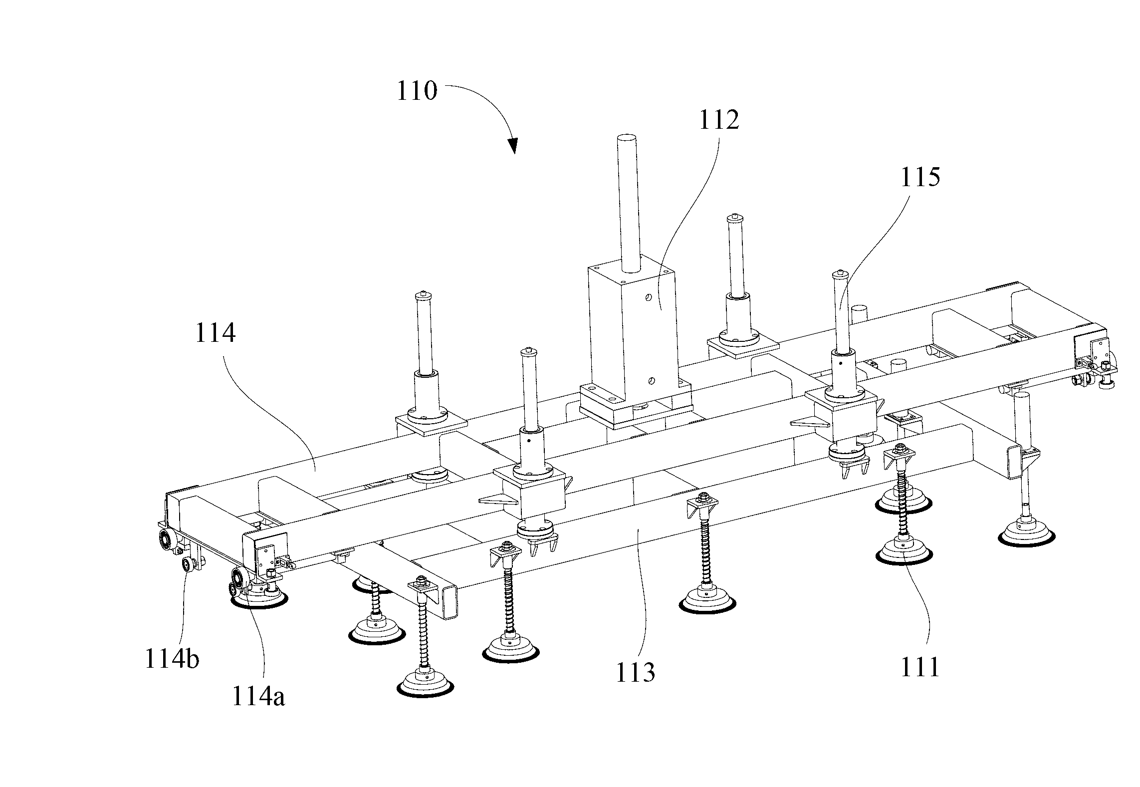
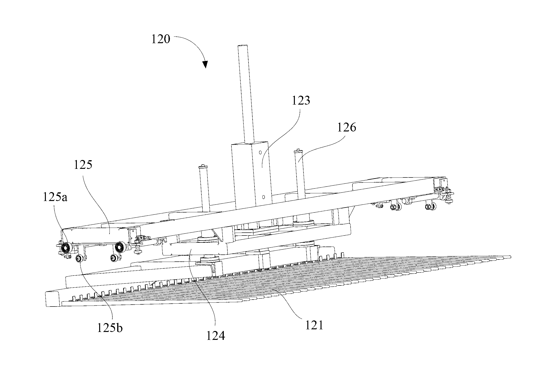
A laser cutter standalone automatic feeding and discharging device comprises a rack mechanism, a suction device, a forking device and a laser cutter workbench arranged below the rack mechanism. The suction device and the forking device are arranged on the rack mechanism, the suction device comprises multiple vacuum suckers and a first air cylinder, the multiple vacuum suckers generate vacuum through airways to realize adsorption of cutting workpieces, the forking device comprises multiple forking teeth through which the cutting workpieces are forked up and put down, the suction device and the forking device can move to be above the laser cutter workbench along the rack mechanism, and the suction device, the forking device and the laser cutter workbench are in vertical or horizontal arrangement. The laser cutter standalone automatic feeding and discharging device can realize a method for standalone automatic feeding and discharging by rationally choosing from the vertical arrangement mode and the horizontal arrangement mode; and by the vertical arrangement mode, a discharging portion can be demounted, and operations of automatic feeding can be realized independently. The invention further provides a laser cutter standalone automatic feeding and discharging method.

Description

【Technical field】 [0001] The invention belongs to the application field of laser cutting machines, in particular to a laser cutting machine single-machine automatic loading and unloading device and method. 【Background technique】 [0002] During the use of the traditional laser cutting machine, the operator needs to place the cutting workpiece to be processed by the laser cutting machine on the designated position of the laser cutting machine workbench, and then the laser cutting machine workbench automatically transports the cut workpiece to be processed to the cutting machine Laser processing is carried out in the processing area. After the cutting workpiece is processed (the cutting workpiece is processed into a part), the laser cutting machine table will be transported out of the processing area (this is the automatic operation step of the laser cutting machine), and then the operator needs to put The workpiece is placed from the laser cutting machine table to the designa...

Claims


Application Information

Patent Timeline
Patent Type & Authority Applications(China)
IPC IPC(8): B23K26/38B23K26/42B23K26/70
Inventor 王观东赵剑罗贵长陈根余陈燚高云峰
Owner SHENZHEN HANS MP LASER TECH CO LTD
Why Eureka
Try Eureka