
Bi-directional barb exiting sliding block mechanism

A technology of two-way barbs and sliders, applied in the field of slider mechanisms, can solve the problems of insufficient strength, unstable work, and low safety of the reverse small shifting block structure 42, and achieve simple structure, convenient processing and assembly, and not easy to wear Effect

Inactive Publication Date: 2013-04-24
MITAC PRECISION TECH(KUNSHAN) CORP
View PDF3 Cites 8 Cited by
  • Summary
  • Abstract
  • Description
  • Claims
  • Application Information

AI Technical Summary

Problems solved by technology

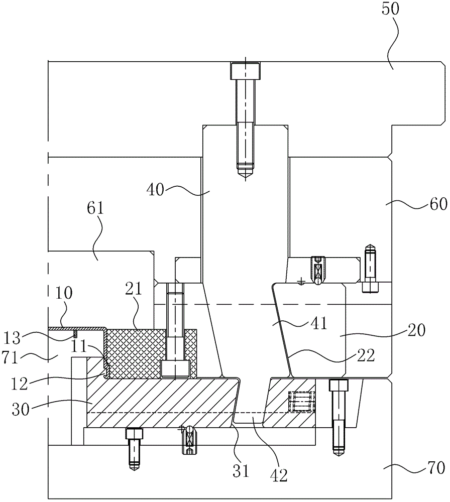
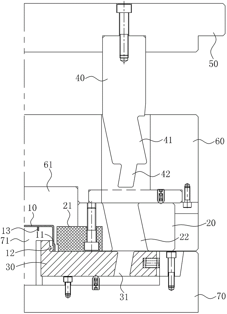
However, due to the two-way barb exit slider mechanism of the prior art, because the shift block 40 is subjected to a large force when opening and closing the mold, the reverse small shift block structure 42 at the front end is not strong enough, and it is very easy to break, and often needs to be demoulded for inspection. and replacement, so the two-way barb exit slider mechanism in the prior art is unstable and less secure, and there are many limitations in practical application

Method used


Image

  • Bi-directional barb exiting sliding block mechanism
  • Bi-directional barb exiting sliding block mechanism
  • Bi-directional barb exiting sliding block mechanism

Examples


Embodiment Construction

[0026] The specific implementation manners of the present invention will be described in further detail below in conjunction with the accompanying drawings.

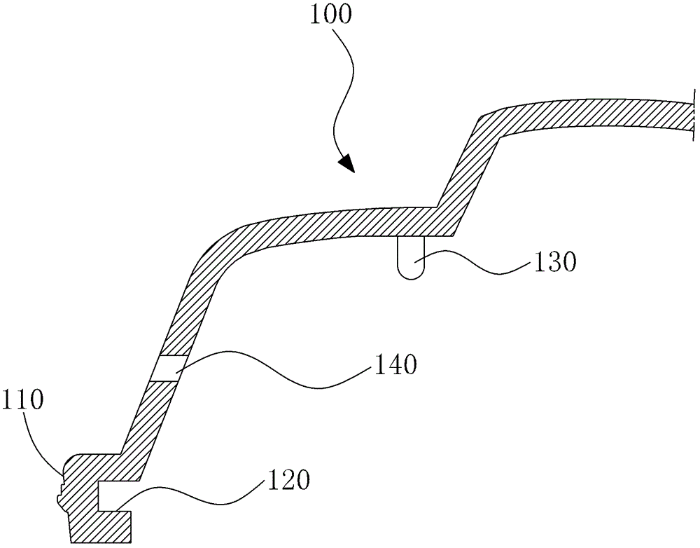
[0027] Please refer to 3, which shows a schematic cross-sectional view of a product with two-way barbs on the side. The product 100 has an outer barb 110 and an inner barb 120 on the side, a rib structure 130 on the inner top surface of the product 100, and a horizontal hole 140 on the side of the product.

[0028] see Figure 4 to Figure 7 As shown, the two-way barb exit slider mechanism of the present invention is applied in a mold for molding the product 100. The mold includes an upper fixing plate 200, a female template 300, a female mold core 310, a male template 400, and a male mold core 410 , is characterized in that the two-way barb exit slider mechanism of the present invention includes:

[0029] An outer slider 600, which is slidably arranged on the master template 300, its front end extends into the cavity t...


PUM


Abstract

The invention relates to a bi-directional barb exiting sliding block mechanism which is applied to a mould. The mould comprises an upper fixing plate, a female mould plate and a male mould plate. The bi-directional barb exiting sliding block mechanism comprise an outer sliding block, a wedge and an inner sliding block, wherein the outer sliding block is arranged on the female mould plate; the front end of the outer sliding block extends into a cavity for shaping the outer-side barb of a product; the rear end of the outer sliding block is provided with an inclined T-shaped slot; the upper end of the wedge is arranged on the upper fixing plate; the lower end of the wedge passes through the female mould plate; the side surface of the wedge is fixedly provided with a T-shaped block in a sliding fit with the inclined T-shaped slot of the outer sliding block; when the mould is opened, the T-shaped block drives the outer sliding block to outwards slide to exit the outer-side barb of the product; the inner sliding block is arranged on the male mould plate in a sliding mode; the front end of the inner sliding block extends into a cavity and bends upwards to shape the inner-side barb of the product; the rear end of the inner sliding block is fixedly provided with an inclined guide pillar which is in the opposite direction with the T-shaped slot; the inclined guide pillar is movably penetrated in the inclined guide hole of the female mould plate; and when the mould is opened, the inclined guide hole drives the inner sliding block by the inclined guide pillar to inwards slide to exit the inner-side barb of the product.

Description

【Technical field】 [0001] The invention relates to a slider mechanism of a mold, in particular to a two-way barb exit slider mechanism. 【Background technique】 [0002] When a plastic product has barbs in the mold opening direction both inside and outside on the same side, generally speaking, the outer barb can use male and female outer mold sliders to withdraw from the barb, while the inner barb can only use oblique pins to realize the withdrawal from molding. , when the product has a rib structure inside, it is difficult to design the oblique pin to withdraw from the inner barb of the forming, and it is necessary to use the slider in the male mold to withdraw from the inner barb of the forming, which cannot be achieved by the ordinary slider mechanism. [0003] see figure 1 and figure 2 , which respectively depict the structure diagram of the prior art two-way barb exit slider mechanism in the mold closing state and the structure diagram of the prior art two-way barb exit...

Claims


Application Information

Patent Timeline
IPC IPC(8): B29C33/42B29C33/44
Inventor 赵志奎
Owner MITAC PRECISION TECH(KUNSHAN) CORP
Learn More