Bottle supporting device

A bottle-supporting and bottle-supporting plate technology is applied in the field of bottle-supporting devices of filling machines, which can solve the problems of large occupied space, increased manufacturing cost, difficult maintenance, etc., and achieves the effects of small occupied space, reduced cost, and simple maintenance.

Active Publication Date: 2013-04-24
GUANGZHOU TECH LONG PACKAGING MACHINERY CO LTD
View PDF7 Cites 7 Cited by
  • Summary
  • Abstract
  • Description
  • Claims
  • Application Information

AI Technical Summary

Problems solved by technology

Due to the large size and high price of the flange, the manufacturing cost is increased. At the same time, since the connecting plate and the bottle support plate are fixed by welding, the connecting plate is easily deformed and scrapped during the welding process, which not only increases the difficulty of manufacturing, but also further increases the manufacturing cost. cost
In addition, due to the large size of the flange plate, the size of the corresponding mounting plate 112 is also large, resulting in a large space occupation; because of high manufacturing difficulty, complicated installation, and even difficult maintenance

Method used


Image

  • Bottle supporting device
  • Bottle supporting device
  • Bottle supporting device

Examples


Embodiment 1

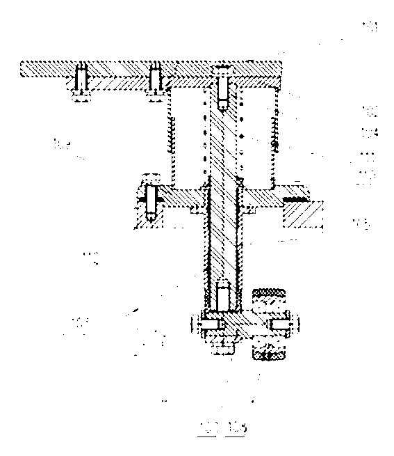
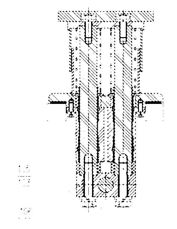
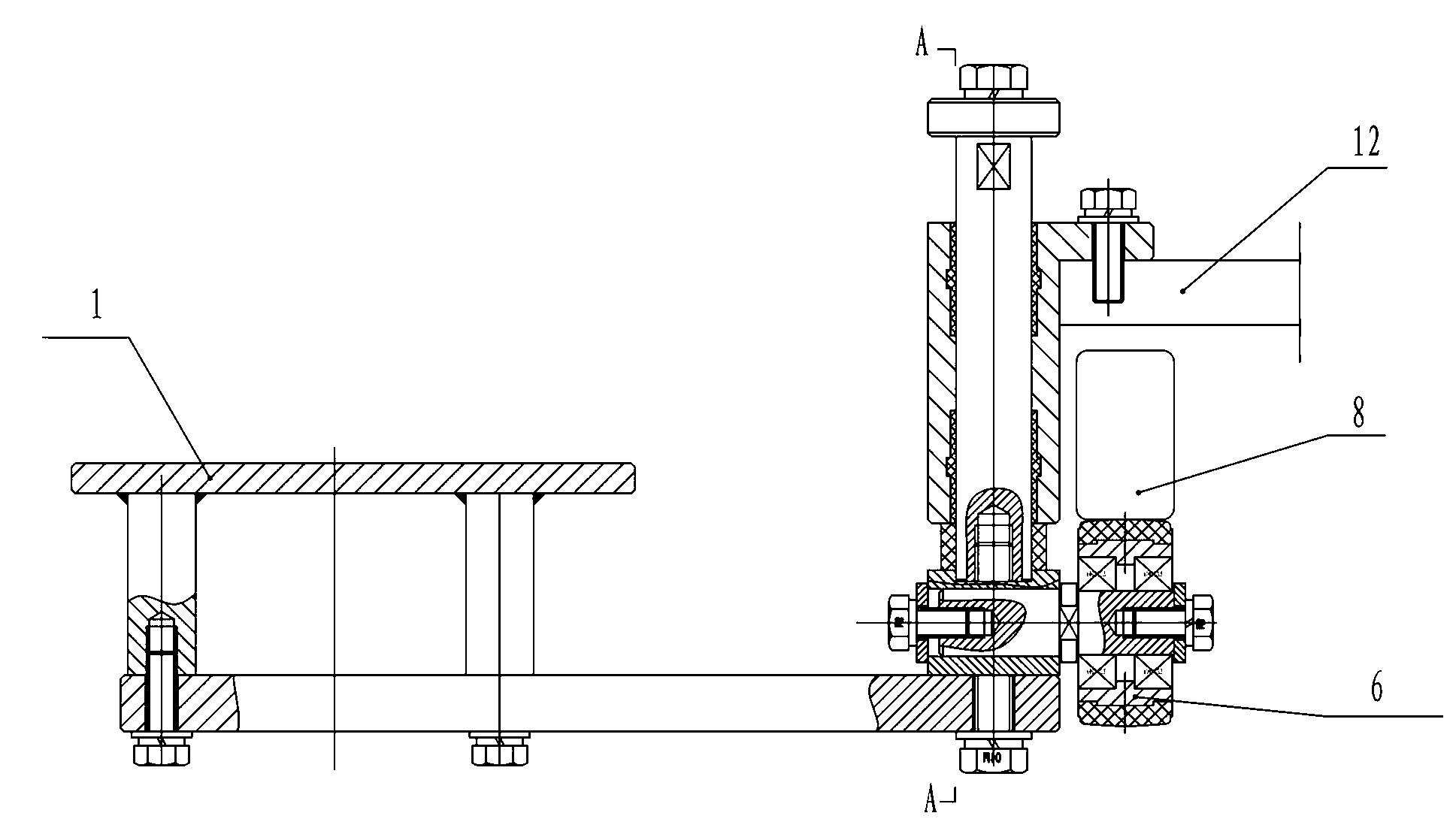
[0011] Embodiment 1: as Figure 3 to Figure 5 As shown, the connecting block 2 that drives the lifting of the bottle support plate 1 is connected to one end of the guide post 4 with the sliding bearing 11 passing through the bearing seat 3, and the other end of the guide post 4 is connected to the limit plate 5 to become one. A lifting device is provided, and the lifting device includes a spring 7 connected between the roller 6 on the connection block 2 and the bearing seat 3 , and the front end of the spring 7 contacts the limit plate 5 . Install the bearing seat 3 on the turntable 12. During the operation of the filling machine, the roller 6 runs on the single guide rail 8 with a height difference. As the trajectory of the guide rail 8 gradually decreases, the roller 6 is pressed down and gradually descends, thereby Drive the guide post 4 to slide downward, and then the guide post 4 drives the bottle support plate 1 to descend. The position plate 5, so the spring 7 is compr...

Embodiment 2

[0014] Embodiment 2: The connection block 2 that drives the bottle support plate 1 up and down is connected to one end of the guide post 4 with the sliding bearing 11 passing through the bearing seat 3, and the other end of the guide post 4 is connected to the limit plate 5 to form one body. The connection block 2 A lifting device is arranged on it, and the lifting device is a roller 6 connected to the connecting block 2 . Install the bearing seat 3 on the turntable 12, the roller 6 moves on the double guide rails, and its upper end and lower end are in contact with the upper guide rail and the lower guide rail with a height difference respectively, and the curve trajectory of the upper guide rail and the lower guide rail is the same. In the middle, as the trajectory of the guide rail gradually decreases, the roller 6 is gradually lowered by the pressure of the upper guide rail, thereby driving the guide column 4 to slide downward, and then the guide column 4 drives the bottle ...

Embodiment 3

[0015] Embodiment 3: The connection block 2 that drives the bottle support plate 1 to lift is connected to one end of the guide post 4 with the sliding bearing 11 passing through the bearing seat 3, and the other end of the guide post 4 is connected to the limit plate 5 to form one body. The connection block 2 A lifting device is arranged on the top, and the lifting device includes a roller 6 connected to the connecting block 2. The lower end of the roller 6 contacts the highest position of the edge of the cam. The cam is connected to the stepping motor, and the bearing seat 3 is installed on the turntable 12. Drive the cam to rotate. When the highest position of the cam edge touches the roller 6, the roller 6 is raised, so that the connecting block 2 rises, and then drives the guide post 4, the limit plate 5 and the bottle support plate 1 to rise; when the cam rotates to the lowest position of the edge , the limiting plate 5, the guide post 4, the connecting block 2 and the bo...


PUM


Abstract

The invention provides a bottle supporting device. The bottle supporting device comprises a bottle supporting plate, wherein a connecting block for driving the bottle supporting plate to lift is connected with one end of a guide column penetrating through a shaft cylinder; the other end of the guide column is integrally connected with a limiting plate; a lifting device is arranged on the connecting block; the lifting device moves to drive the connecting block to lift, so that the bottle supporting plate, the guide column and the limiting plate are driven to lift. As the bottle supporting device provided by the invention is small in volume and simple in structure, and does not need a flange plate, the bottle supporting device provided by the invention has the advantages of low cost, small space usage, and simplicity in mounting and maintenance; and meanwhile, as objects can be fixed without welding, the objects cannot be deformed and declared worthless due to welding, therefore, the cost is further reduced.

Description

technical field [0001] The invention relates to the technical field of liquid filling, in particular to a bottle supporting device of a filling machine. Background technique [0002] During the liquid filling process, it is the bottle supporting device in the filling machine that drives the container up and down. The mouth is in contact with the filling head for filling, and after the filling is completed, it descends and resets. [0003] Currently used bottle holders, such as figure 1 and figure 2 As shown, the bottle holder plate 101 is included, the bottle holder plate 101 is connected to one end of the guide post 104 with the sliding bearing 103 through the connecting plate 102, the guide post 104 passes through the bearing seat 105, and its other end is connected to the connection block 106, the connection block 106 links to each other with roller 108 by shaft 107, and flange plate 109 is fixed on the outer side of bearing block 105, and spring seat 110 is arranged ...

Claims


Application Information

Patent Timeline
Patent Type & Authority Applications(China)
IPC IPC(8): B67C3/24
Inventor 李正良樊缔黄丰山
Owner GUANGZHOU TECH LONG PACKAGING MACHINERY CO LTD
Why Eureka
Try Eureka