Filling machine

A technology of filling machine and transmission device, which is applied in the field of bottle feeding screw mechanism, which can solve the problems of reducing work efficiency, increasing production cost, and being unable to adjust the vertical height and horizontal position of the bottle feeding screw, so as to improve labor efficiency and bottle feeding The effect of orderly operation and lower production cost

Active Publication Date: 2013-04-24
GUANGZHOU TECH LONG PACKAGING MACHINERY CO LTD
View PDF6 Cites 3 Cited by
  • Summary
  • Abstract
  • Description
  • Claims
  • Application Information

AI Technical Summary

Problems solved by technology

[0003] However, the bottle-feeding screw mechanism in the currently used filling machine cannot adjust the vertical height and horizontal position of the bottle-feeding screw before conveying into the bottle. Therefore, depending on the container, the bottle-feeding screw mechanism needs to be replaced again. So that the container and the bottle-feeding screw mechanism have a suitable horizontal position and vertical height, and ensure that the bottle-feeding actions are carried out in an orderly and stable manner
Replacing the entire bottle feeding screw mechanism according to different container types not only greatly increases production costs, but also reduces work efficiency

Method used


Image

  • Filling machine
  • Filling machine
  • Filling machine

Examples


Embodiment 1

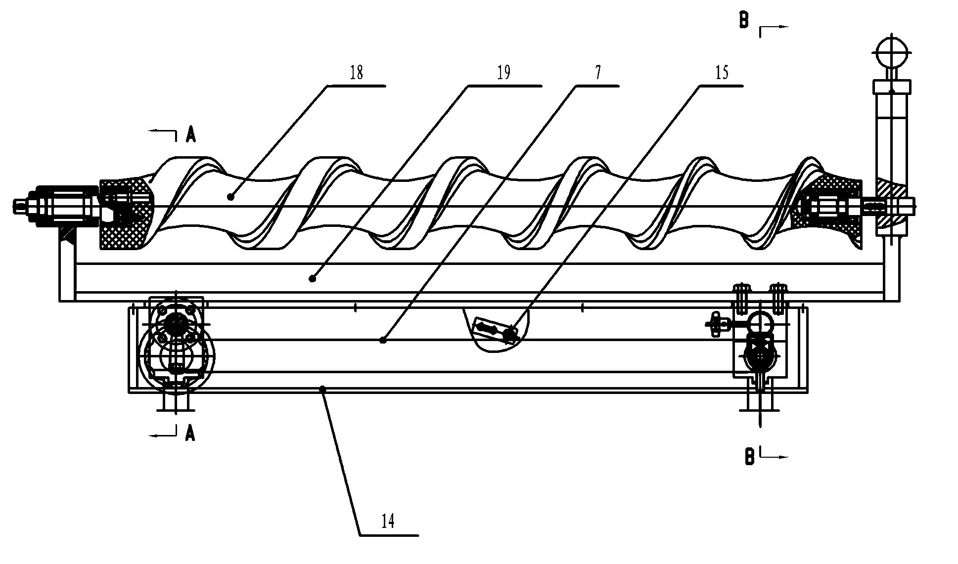
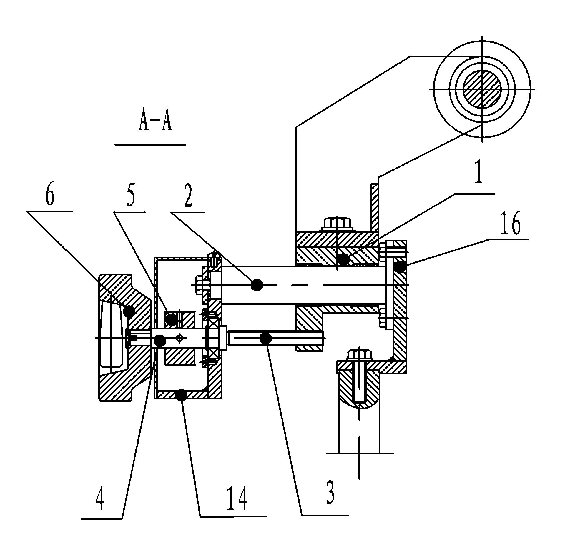
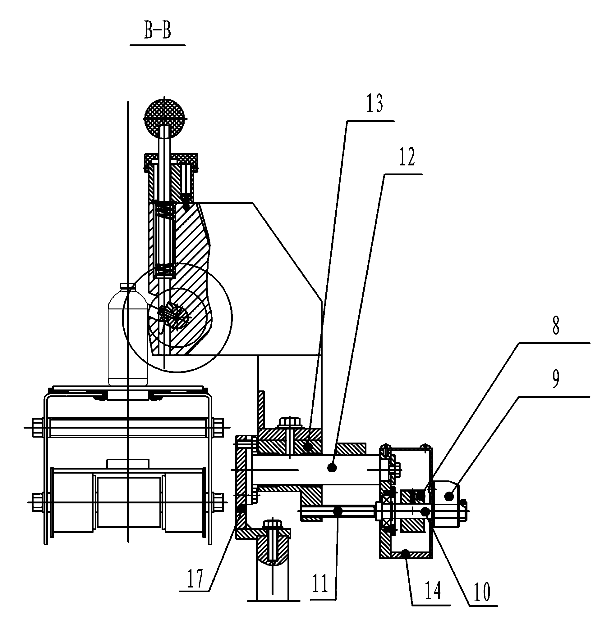
[0010] Embodiment 1: as Figure 1 to Figure 3 As shown, a filling machine includes a bottle feeding screw 18, the bottle feeding screw 18 is installed on a support frame 19, the support frame 19 is fixed on the left sliding seat 1 and the right sliding seat 13, and the left sliding seat 1 is installed on the left guide On the rod 2, the extended part of the left sliding seat 1 is connected to one end of the left rotating screw 3, and the other end of the left rotating screw 3 is fixed to the left rotating shaft 4, and the driving wheel 5 is fixed on the left rotating shaft 4, and one end of the left rotating shaft 4 is connected to control the left rotating shaft 4 The rotating adjustment hand wheel 6, the driving wheel 5 is connected with the driven wheel 8 through the synchronous belt 7 or the chain, the driven wheel 8 is installed and fixed on the right rotating shaft 10, the right rotating shaft 10 is connected to one end of the right rotating screw rod 11, and the position...

Embodiment 2

[0013] Embodiment 2: In the filling machine, the support frame 19 equipped with the bottle feeding screw 18 is fixed on the sliding seat, the sliding seat is installed on the guide rod, the extended part of the sliding seat is installed on the flat surface of the rack, and the rack Mesh with the gear, and the gear is connected with the stepper motor. The horizontal position adjustment mechanism of the bottle-feeding screw is placed in the middle of the bottle-feeding screw support frame. The stepper motor controls the gear rotation to drive the rack to slide horizontally, so that the rack drives the sliding seat to slide horizontally, and then the sliding seat drives the support frame 19 to slide horizontally. To complete the bottle-feeding screw rod 18 horizontal position adjustment actions.

Embodiment 3

[0014] Embodiment 3: The sliding seat is installed on the guide rod, the extended part of the sliding seat is connected with the rotating screw, and the device for controlling the rotation of the screw is a stepping motor. The horizontal position adjustment mechanism of the bottle feeding screw is placed in the middle of the bottle feeding screw support frame, and the stepping motor or adjusting handwheel works to drive the rotating screw to rotate, and the rotating screw screw drive controls the sliding seat to slide horizontally on the guide rod, thereby driving the support frame 19 slides horizontally, and then drives the bottle-entry screw rod 18 to move horizontally to complete the horizontal position adjustment action.

[0015] The device for controlling the rotation of the left shaft 4, the gear and the rotating screw respectively is the adjusting hand wheel 6 or a stepping motor.


PUM


Abstract

The invention relates to a filling machine. The filling machine comprises a bottle feeding screw rod, wherein the bottle feeding screw rod is mounted on a supporting frame; the supporting frame is fixed on a sliding seat; the sliding seat is connected with a guide rod; the extending part of the sliding seat is connected with a transmission device for controlling sliding of the sliding seat; the transmission device controls the sliding seat to horizontally slide along a guide rail so as to drive the supporting frame to slide to drive the bottle feeding screw rod to horizontally move. By adoption of the filling machine, the horizontal position of the bottle feeding screw rod of the filling machine can be adjusted easily, the whole set of bottle feeding screw rod mechanism during exchange of the filling machine is avoided, the production cost is greatly reduced, the labor efficiency is improved, and the bottle feeding action is performed sequentially, accurately and stably during operation of the filling machine.

Description

technical field [0001] The invention relates to a filling machine, in particular to a bottle feeding screw mechanism in the filling machine. Background technique [0002] In the field of packaging industry, various types of bottle-feeding screw mechanisms have been widely used in filling machines, which can supply containers and objects to a given station one by one at a certain speed, direction and spacing according to process requirements. The bottle feeding screw mechanism improves labor efficiency and reduces manpower consumption. At the same time, it also makes the container move in an orderly and stable state, ensuring the accuracy of delivery. [0003] However, the bottle-feeding screw mechanism in the currently used filling machine cannot adjust the vertical height and horizontal position of the bottle-feeding screw before conveying into the bottle. Therefore, depending on the container, the bottle-feeding screw mechanism needs to be replaced again. So that the cont...

Claims


Application Information

Patent Timeline
Patent Type & Authority Applications(China)
IPC IPC(8): B67C3/24
Inventor 王波樊缔
Owner GUANGZHOU TECH LONG PACKAGING MACHINERY CO LTD
Why Eureka
Try Eureka