Pressure relief method aimed at strata behaviors of gob side entries of fully mechanized caving faces

A technology of roadway and work, which is applied in mining equipment, mining equipment, earth-moving drilling, etc., can solve the problems of uncontrolled mine pressure and roadway deformation.

Inactive Publication Date: 2013-04-24
DATONG COAL MINE GRP
View PDF0 Cites 10 Cited by
  • Summary
  • Abstract
  • Description
  • Claims
  • Application Information

AI Technical Summary

Problems solved by technology

These are all measures taken passively for the smooth outward advancement of the working face after the emergence of mine pressure. Although it has played a certain role in weakening the emergence of mine pressure, the deformation of the roadway is still very serious due to too much pressure, and the mine pressure cannot be obtained. Actual control cannot fundamentally solve the problem of mine pressure phenomenon from the source

Method used


Image

  • Pressure relief method aimed at strata behaviors of gob side entries of fully mechanized caving faces
  • Pressure relief method aimed at strata behaviors of gob side entries of fully mechanized caving faces
  • Pressure relief method aimed at strata behaviors of gob side entries of fully mechanized caving faces

Examples


Embodiment 1

[0016] A pressure relief method for fully mechanized caving work faced with the appearance of mine pressure in empty roadways, comprising the following steps:

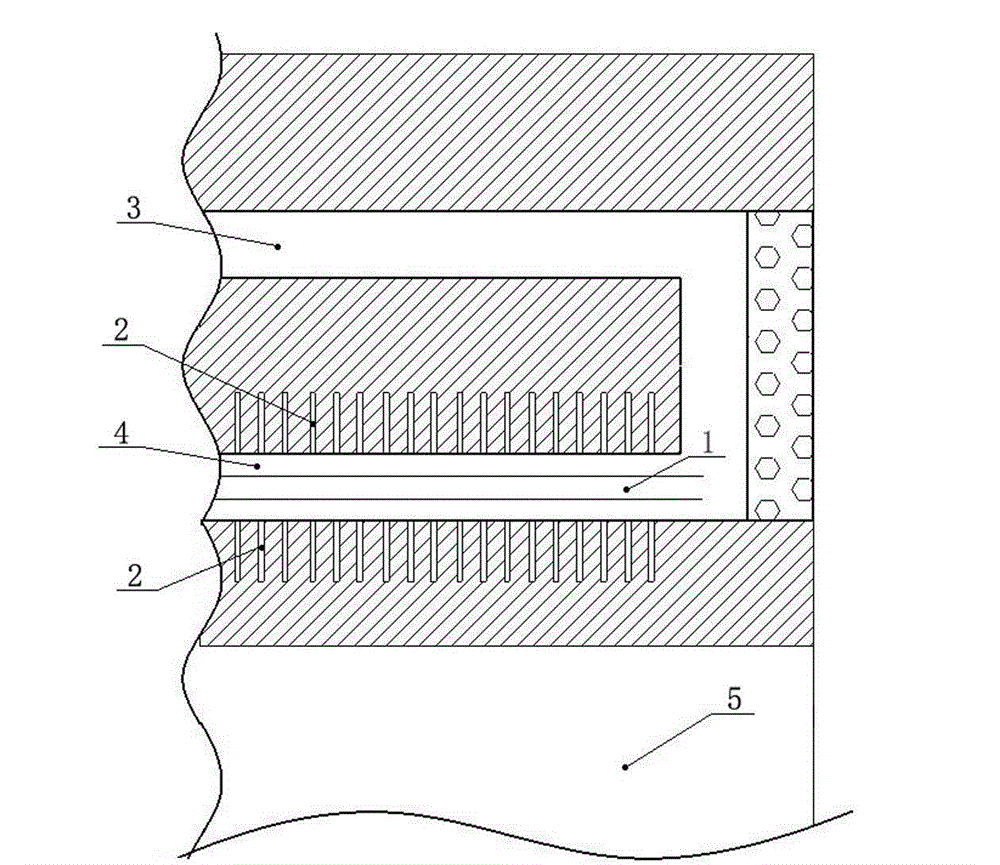
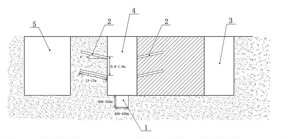
[0017] 1) Construction pressure relief groove: construct pressure relief groove 1 from inside to outside on the bottom plate of the roadway, and arrange pressure relief groove 1 at the center line of the bottom plate of the roadway.

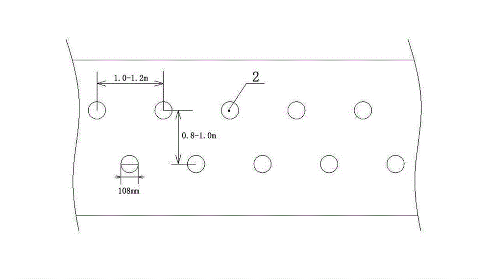
[0018] 2) Construction of pressure relief holes: construct two rows of pressure relief holes 2 from top to bottom on both sides of the roadway, each row of pressure relief holes 2 has a diameter of 108mm, a hole depth of 17m, and an upward inclination of 5° 1. The hole spacing is 1.2m; the row spacing of two adjacent rows of pressure relief holes 2 is 0.8m, and the two adjacent rows of pressure relief holes 2 are arranged with triple eyelets.

Embodiment 2

[0020] A pressure relief method for fully mechanized caving work faced with the appearance of mine pressure in empty roadways, comprising the following steps:

[0021] 1) Construction pressure relief groove: construct pressure relief groove 1 from the inside to the outside on the bottom plate of the roadway.

[0022] 2) Construction of pressure relief holes: construct three rows of pressure relief holes 2 from top to bottom on both sides of the roadway, each row of pressure relief holes 2 has a diameter of 108mm, a hole depth of 15m, and an upward inclination of 4° 1. The hole spacing is 1.0m; the row spacing of two adjacent rows of pressure relief holes 2 is 1.0m, and the two adjacent rows of pressure relief holes 2 are arranged with triple eyelets.

Embodiment 3

[0024] A pressure relief method for fully mechanized caving work faced with the appearance of mine pressure in empty roadways, comprising the following steps:

[0025] 1) Construction of pressure relief groove: construct pressure relief groove 1 from inside to outside on the roadway floor of the adjacent roadway. Pressure relief groove 1 is arranged at the center line of the roadway floor. Pressure relief groove 1 is 500mm deep and 425mm wide;

[0026] 2) Construction of pressure relief holes: construct four rows of pressure relief holes 2 from top to bottom on both sides of the roadway, each row of pressure relief holes 2 has a diameter of 108mm, a hole depth of 13m, and an upward inclination of 6° 1. The hole spacing is 1.1m; the row spacing of the two adjacent rows of pressure relief holes 2 is 0.9m, and the two adjacent rows of pressure relief holes 2 are arranged with triple eyelets.


PUM


Abstract

The invention relates to a pressure relief method aimed at strata behaviors of gob side entries of fully mechanized caving faces and solves the problem of the absence of effective methods for strata behaviors of mines at present. The method comprises building a pressure relief groove which is 500mm to 550mm deep and 400mm to 450mm wide on a center line of a gob side entry bottom plate, and building at least two rows of pressure relief holes which are 13mm to 17mm deep and incline upwards by 4 degrees to 6 degrees from top to bottom on two sides of the gob side entry, wherein the two adjacent rows of the pressure relief holes are arranged in a triangular mode. According to the pressure relief method, the stress distribution of gob side entries is transferred in advance through pressure relief technologies of building of the pressure relief groove and the pressure relief holes and the like, strata behaviors of gob side entries are weakened, the passivity is converted into the initiative, the problem is solved fundamentally from the source, and the mine pressure is controlled.

Description

technical field [0001] The invention relates to the technical field of coal mine mining, in particular to a pressure relief method for fully-mechanized caving work faced with the appearance of mine pressure in empty roadways. Background technique [0002] In the process of coal mining, when a fully-mechanized mining face is mined, the working face becomes a goaf, then in the adjacent fully-mechanized mining face of the goaf, a roadway next to the goaf is the adjacent Empty alleyway. Because there are various equipment placed in the machine lane, the wind lane is generally selected as the air lane, such as figure 1 shown. In the fully mechanized caving face, the roadway near the gob is affected by the mine pressure, resulting in strong mine pressure phenomenon, serious section shrinkage, side drum, bottom drum, roof sinking, etc., resulting in roadway section, especially the advance support The cross-section of the road section is continuously reduced, which brings safety ...

Claims


Application Information

Patent Timeline
Patent Type & Authority Applications(China)
IPC IPC(8): E21F17/00
Inventor 赵军张有喜靳建顺李俊成杨智文鲍永生李向峰李英蔡海聂仕义刘建斌赵春珍
Owner DATONG COAL MINE GRP
Why Eureka
Try Eureka