Valve mechanism

A valve mechanism and hydraulic tappet technology, which is applied in mechanical equipment, engine components, machines/engines, etc., can solve the problem that the valve phase cannot be adjusted and precisely controlled, and the valve mechanism structure cannot be realized. Bloated and complex problems, to achieve the effect of being conducive to rapid implementation, flexible and variable design, and simple structure

Active Publication Date: 2013-04-24
HANGZHOU BRANCH ZHEJIANG GEELY AUTOMOBILE RES INST +2
View PDF6 Cites 7 Cited by
  • Summary
  • Abstract
  • Description
  • Claims
  • Application Information

AI Technical Summary

Problems solved by technology

[0004] Most of the traditional variable-lift valve mechanisms use two or more cam mechanisms with different lifts to match the corresponding valve lifters to achieve different valve lifts. Due to the large number of cam drive mechanisms, the valve The mechanism structure is bloated and complicated, and it is prone to failure, which is incompatible with the current technological development trend of streamlining and integrating engines
The combination of multiple cam drive mechanisms can only achieve multi-level changes in valve lift, but cannot achieve stepless adjustment. More cam driving mechanisms will inevitably make the valve mechanism more complicated
In addition, the traditional valve mechanism can only follow the cam drive mechanism to open or close the valve, and cannot realize the diversified adjustment and precise control of the valve phase, resulting in a single engine performance, which cannot meet the requirements of various working conditions

Method used


Image

  • Valve mechanism

Examples


Embodiment Construction

[0043] In order to make the purpose, technical solutions and advantages of the embodiments of the present invention more clear, specific embodiments will be described in detail below with reference to the accompanying drawings.

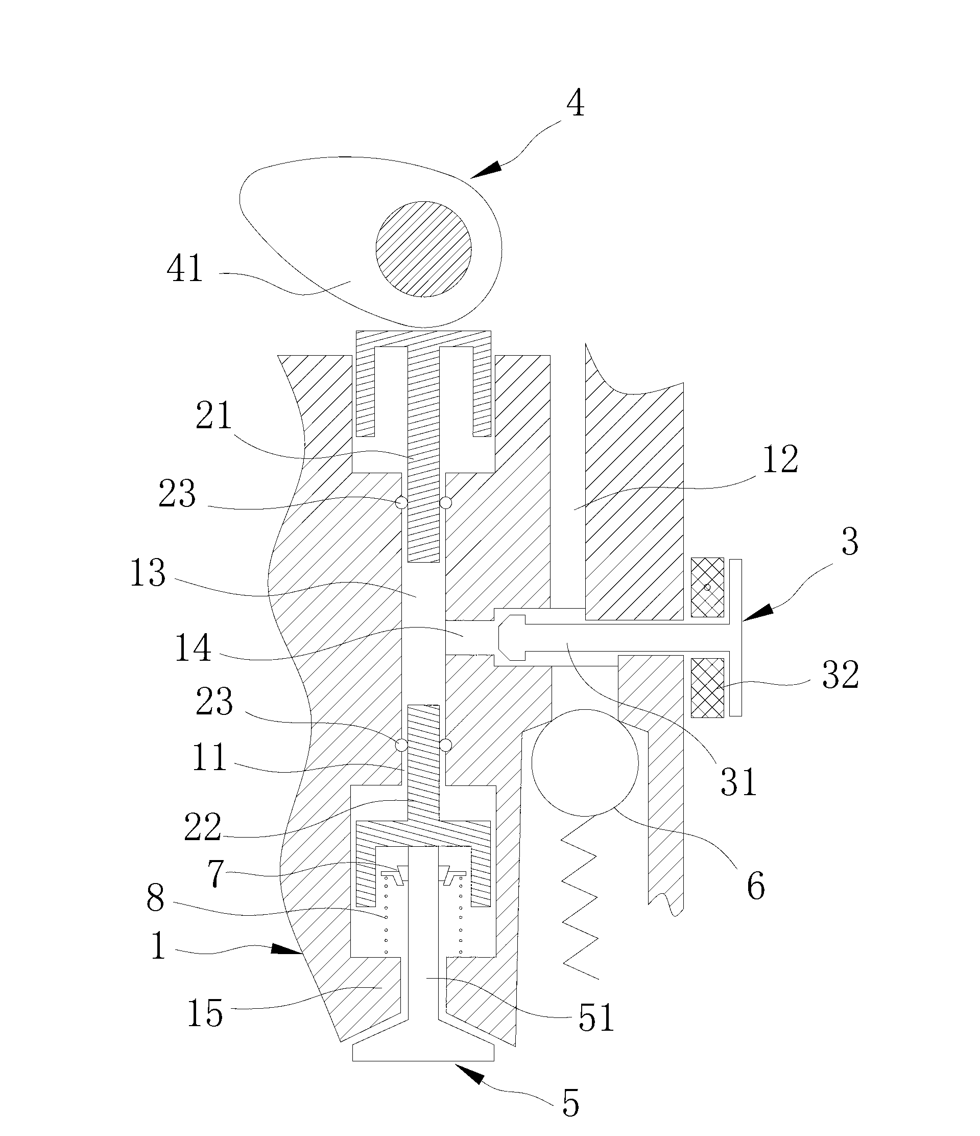
[0044] Please refer to figure 1 , is a structural schematic diagram of the valve mechanism of the present invention, as shown in the figure, the valve mechanism of the present invention mainly includes: a cylinder head 1, which is provided with a passage 11 and a high-pressure oil passage 12; a first hydraulic tappet 21 and a second hydraulic tappet 22. It can be slidably arranged at both ends of the passage 11. The first hydraulic tappet 21, the second hydraulic tappet 22 and the inner wall of the passage 11 enclose a hydraulic chamber 13, and the hydraulic chamber 13 communicates with the high-pressure oil passage 12 through the connecting oil passage 14 The switch valve 3 is located in the connecting oil passage 14 and controls the on-off of the co...


PUM


Abstract

The invention discloses a valve mechanism which comprises a cylinder cover, a first hydraulic tappet, a second hydraulic tappet, a switch valve, a drive part, and a valve. The cylinder cover is provided with a passage and a high-pressure oil duct, the first hydraulic tappet and the second hydraulic tappet are respectively and slidingly arranged at two ends of the passage, the first hydraulic tappet, the second hydraulic tappet and the inner wall of the passage enclose to form a hydraulic cavity, the hydraulic cavity is communicated with the high-pressure oil duct through a connecting oil duct, the switch valve is arranged on the connecting oil duct and controls the on-off of the connecting oil duct, the drive part is connected with the first hydraulic tappet and drives the first hydraulic tappet to slide in the passage, and the valve is connected onto the second hydraulic tappet. By the aid of the valve mechanism, stepless regulation of valve lift and valve control can be achieved, and the valve mechanism is simple in structure and low in cost.

Description

technical field [0001] The invention relates to the technical field of engine gas distribution devices, in particular to a valve mechanism. Background technique [0002] Engine technology has been widely used in vehicles, ships, airplanes and other vehicles. A traditional engine may include a crank-and-rod mechanism, a gas distribution mechanism, a fuel supply system, an ignition system, a cooling system, and a lubrication system, etc., wherein the gas distribution mechanism is mainly responsible for inputting fuel gas mixture into the engine and removing exhaust gas. The valve mechanism is an important part of the valve mechanism, and its operation, especially the adjustment and control of the valve lift and valve phase, will seriously affect the working performance and efficiency of the entire engine. [0003] In actual work, according to various working conditions, the load rate of the engine is also different. The working efficiency of the engine under the high-load wor...

Claims


Application Information

Patent Timeline
Patent Type & Authority Applications(China)
IPC IPC(8): F01L13/00F01L1/34
Inventor 王海龙郭晓瑞马文亮李慧军由毅赵福全
Owner HANGZHOU BRANCH ZHEJIANG GEELY AUTOMOBILE RES INST
Why Eureka
Try Eureka