Method for improving reliability of main engine of oil-free screw compressor, and axial bearing locking structure

An axial bearing and compressor technology, which is applied to machines/engines, components of pumping devices for elastic fluids, mechanical equipment, etc. The assembly process is simple, the mechanical reliability is improved, and the process is controllable.

Inactive Publication Date: 2013-04-24
NANJING COMPRESSOR
View PDF5 Cites 0 Cited by
  • Summary
  • Abstract
  • Description
  • Claims
  • Application Information

AI Technical Summary

Problems solved by technology

[0003] The purpose of the present invention is to solve the problem that the lock nut of the axial bearing of the main engine of the oil-free screw compressor is installed on the outside of the synchronous gear, which makes it inconvenient to adjust the clearance of the synchronous gear after the nut is locked, and the working condition is deteriorated due to the

Method used


Image

  • Method for improving reliability of main engine of oil-free screw compressor, and axial bearing locking structure
  • Method for improving reliability of main engine of oil-free screw compressor, and axial bearing locking structure

Examples


Embodiment 1

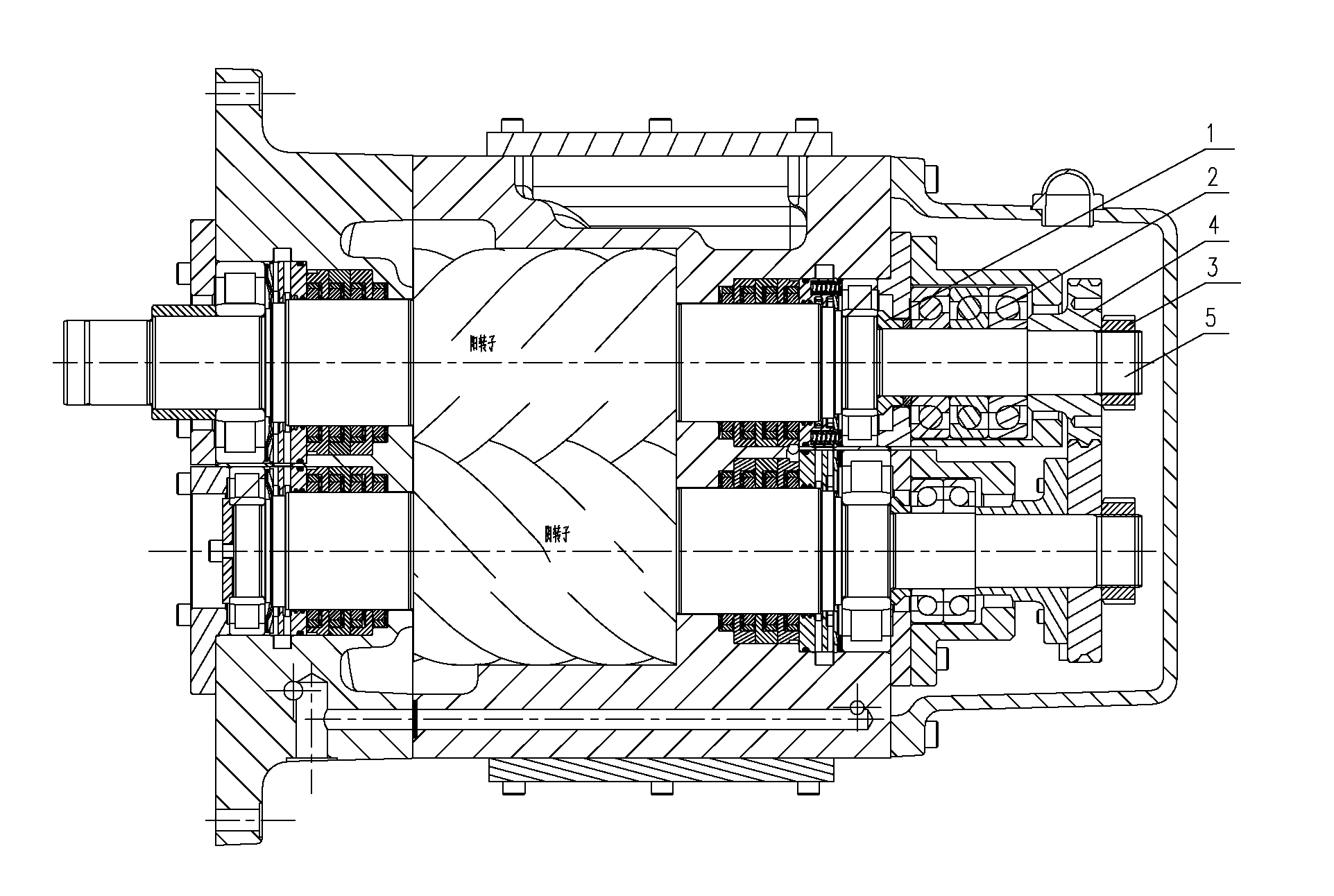
[0018] A method to improve the reliability of an oil-free screw compressor. It changes the installation position of the locking round nut and the synchronous gear on the rotor shaft, so that the locking round nut is installed next to the axial bearing, and the locking round nut is directly pressed on the On the inner shaft ring of the axial bearing, it is transmitted to the outer shaft ring through balls, and finally to the body through the outer shaft ring, so that the synchronous gear is not affected by the axial thrust during the working process, and the work of the synchronous gear is improved. The purpose of the condition is to prolong its service life and improve the reliability of the compressor. The synchronous gear includes a synchronous driving gear installed on the male rotor shaft and a synchronous driven gear installed on the female rotor shaft, and the locking round nut also includes The locking round nut, the axial bearing also includes the axial bearing install...

Embodiment 2

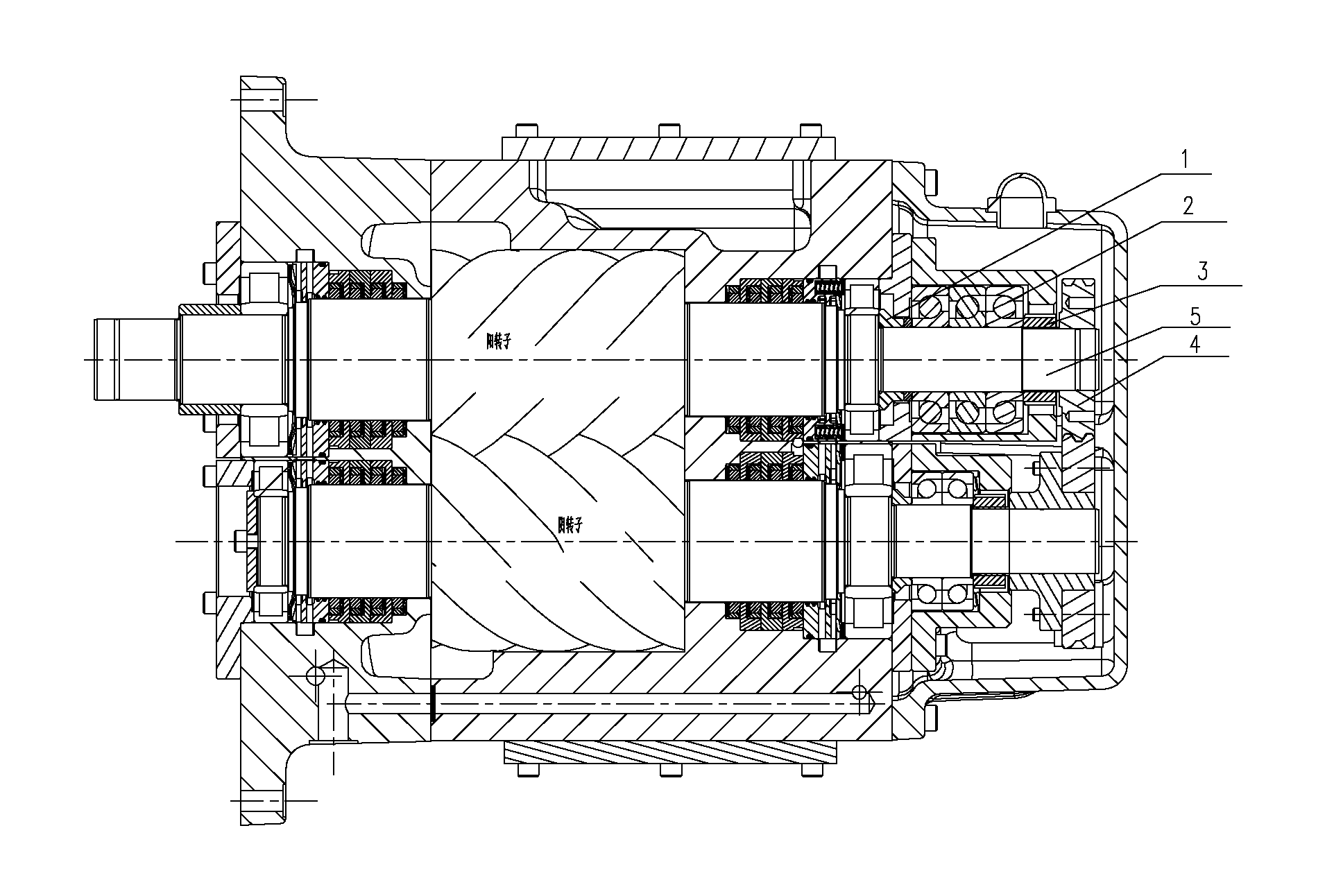
[0020] Such as figure 2 shown.

[0021] A locking structure for the axial bearing of the main engine of an oil-free screw compressor, which is mainly composed of an adjusting pad 1, an axial bearing 2, a locking round nut 3 and a synchronous gear 4, and the adjusting pad 1 is connected with the rotor shaft (including the male rotor and the female rotor) Rotor (with the same structure) offsets the left end of the axial bearing 2 to locate the left end. The axial bearing 2 is installed and positioned on the rotor shaft 5 between the adjusting pad 1 and the locking round nut 3. The locking round nut 3 realizes the axial The right end of the bearing is fixed, and the synchronous gear 4 is installed on the rotor shaft 5, the outside of the locking round nut 3. Such as figure 2 shown. In the present invention, the locking round nut 3 is moved between the axial bearing 2 and the synchronous gear 4, and the assembly is to adjust the rotor exhaust end surface clearance (the adjust...


PUM


Abstract

The invention discloses a method for improving the reliability of a main engine of an oil-free screw compressor and an axial bearing locking structure. The method and the axial bearing locking structure are characterized in that the method comprises the step of changing the installation position of a locking nut on a rotor to ensure that the locking nut directly presses an axial bearing instead of pressing a synchromesh gear; and the locking structure mainly comprises an adjusting pad (1), the axial bearing (2), the locking round nut (3) and the synchromesh gear (4), wherein the axial bearing (2) is arranged and positioned on a rotor shaft (5) between the adjusting pad (1) and the locking round nut (3), and the synchromesh gear (4) is arranged on the rotor shaft (5) and outside the locking round nut (3). According to the invention, the functional requirements and the installation sequence are synchronous, so that the installation and the adjustment are very conveniently and rapidly carried out in a synchronous manner, and the head of the motor engine reliability is improved at the same time.

Description

technical field [0001] The present invention relates to an oil-free screw compressor, especially a method for improving the reliability of the whole machine by improving the stress state of the synchronous transmission gear to prolong the service life of the synchronous gear and the locking structure of the axial bearing, specifically A method for improving the reliability of an oil-free screw compressor and an axial bearing locking structure. Background technique [0002] Generally, the locking of the axial bearing of the main engine of an oil-free screw compressor is set at the outermost end, that is, the outer side of the synchronous gear. Sufficient safety clearance, so it is inconvenient to adjust the clearance after locking first. The axial bearing is installed on the shaft of the female and male rotors in the oil-free screw head, and its functional requirements mainly include two points: 1. The rotor and the end face of the casing (moving and static parts) ensure a s...

Claims


Application Information

Patent Timeline
IPC IPC(8): F04C29/00F04C18/16
Inventor 徐辉金宏春夏苏建蔡建红
Owner NANJING COMPRESSOR
Why Eureka
Try Eureka