Hydraulic oil radiating system and engineering machinery

A technology of heat dissipation system and hydraulic system, which is applied in the direction of fluid pressure actuation system components, mechanical equipment, fluid pressure actuation devices, etc., to ensure the effect of normal operation

Inactive Publication Date: 2013-04-24
SANY AUTOMOBILE MFG CO LTD
View PDF12 Cites 11 Cited by
  • Summary
  • Abstract
  • Description
  • Claims
  • Application Information

AI Technical Summary

Problems solved by technology

[0004] In view of this, the present invention proposes a hydraulic oil cooling system and construction machinery to solve the problems of energy s

Method used


Image

  • Hydraulic oil radiating system and engineering machinery

Examples


Example Embodiment

[0018] It should be noted that the embodiments of the present invention and the features in the embodiments can be combined with each other if there is no conflict. Hereinafter, the present invention will be described in detail with reference to the drawings and in conjunction with the embodiments.

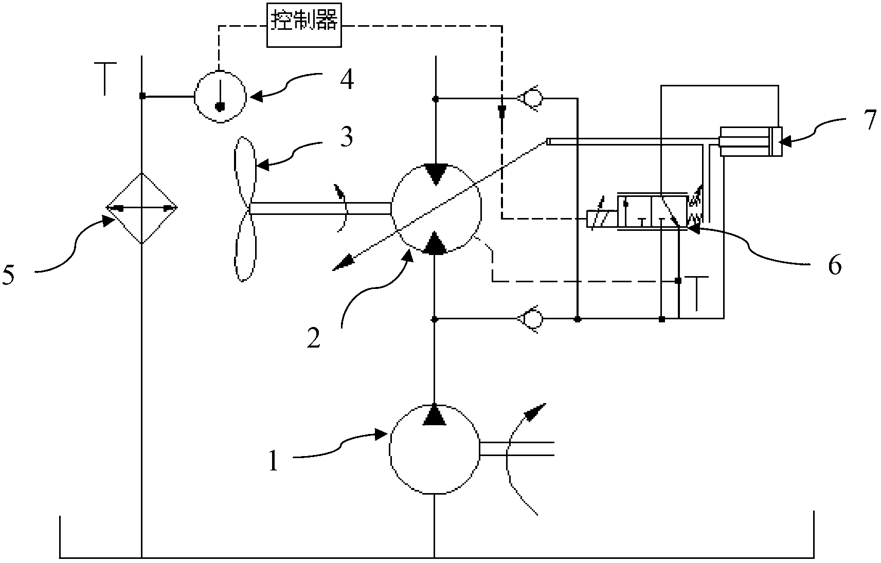
[0019] Such as figure 1 As shown, a hydraulic oil heat dissipation system, which is located in the hydraulic system of a construction machine, includes a hydraulic oil radiator 5, a fan 3, an air-cooled motor 2, a controller, a temperature sensor 4, and a hydraulic pump 1. The air-cooled motor 2 is a variable hydraulic motor, including a displacement control oil cylinder 7 and an electric proportional control valve 6. The temperature sensor 4 is installed at the oil inlet of the hydraulic oil radiator 5 to detect the temperature of the hydraulic oil at the oil inlet of the hydraulic oil radiator 5. The air-cooled motor 2 drives the fan 3 to dissipate heat from the hydraulic oil rad...


PUM


Abstract

The invention discloses a hydraulic oil radiating system which comprises a hydraulic oil radiator, a fan, an air cooling motor, a controller and a temperature sensor. The temperature sensor is used for detecting the temperature of an oil inlet or an oil outlet of the hydraulic oil radiator, the air cooling motor drives the fan to cooling the hydraulic oil radiator, and the controller controls rotation speed of the fan according to signals of the temperature sensor. The invention further provides engineering machinery. Energy saving, emission reduction and noise reduction can be achieved while guaranteeing regular work of the hydraulic system of the engineering machinery.

Description

technical field [0001] The invention relates to the field of construction machinery, in particular to a hydraulic oil cooling system and construction machinery. Background technique [0002] At present, in the field of construction machinery, the hydraulic oil cooling system is the core of the entire cooling system. After the hot hydraulic oil is cooled by the radiator, it exchanges heat with the hydraulic oil in the oil tank, so that the temperature of the entire hydraulic system can be controlled in the system and each power component. within the acceptable range. [0003] Existing hydraulic oil heat dissipation systems generally use a quantitative motor to drive the fan to rotate. When the displacement of the quantitative motor is constant, the fan speed is constant, and the fan always works in a cooling power state. The hydraulic oil cooling device has no feedback adjustment, and when the hydraulic system generates little heat and the ambient temperature is low, it will...

Claims


Application Information

Patent Timeline
IPC IPC(8): F15B21/04
Inventor 罗福胜李建涛张涛
Owner SANY AUTOMOBILE MFG CO LTD
Why Eureka
Try Eureka