
Stamping part connecting fastening structure

A technology for connecting fastening and sheet metal parts. It is applied in the direction of connecting components, bolts, mechanical equipment, etc. It can solve the problems of inconvenient maintenance, nuts are easy to fall off, and increase the assembly process, etc., to achieve effective limit function and ensure tight connection. , The effect of low manufacturing cost

Inactive Publication Date: 2013-04-24
力帆科技(集团)股份有限公司
View PDF6 Cites 12 Cited by
  • Summary
  • Abstract
  • Description
  • Claims
  • Application Information

AI Technical Summary

Problems solved by technology

The main problems that exist are: (1) after the bolts and nuts are disassembled, the nuts are easy to fall off: (2) if Figure 11 As shown, limited by the installation position, it is often necessary to weld the nut 7 on one of the sheet metal parts. The nut 7 is a projection welding nut, which increases the assembly process; (3) when the bolt is fastened, it is often used with the help of a pneumatic or electric sleeve Due to the large torque of the power tool, the bolts often have forced tightening phenomena such as tooth extraction and threading, which brings great inconvenience to the secondary maintenance; (4) For optional parts such as shelves and side boxes that are often disassembled, The user needs to disassemble frequently, and the user generally uses a bayonet wrench, which is easy to wear the edge of the hexagonal head, resulting in difficulty in disassembly and even damage

Method used


Image

  • Stamping part connecting fastening structure
  • Stamping part connecting fastening structure
  • Stamping part connecting fastening structure

Examples


Embodiment Construction

[0028] In the following, the present invention will be further described in detail through embodiments and in conjunction with the drawings:

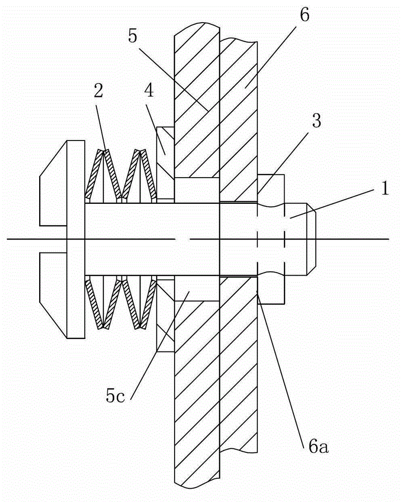
[0029] Such as figure 1 The shown connection and fastening structure of sheet metal parts is composed of a first sheet metal part 5, a second sheet metal part 6 and a fastening connection component. The fastening connection component consists of a connecting rod 1, a return spring 2, and a limit pin 3 and 4 flat pads.

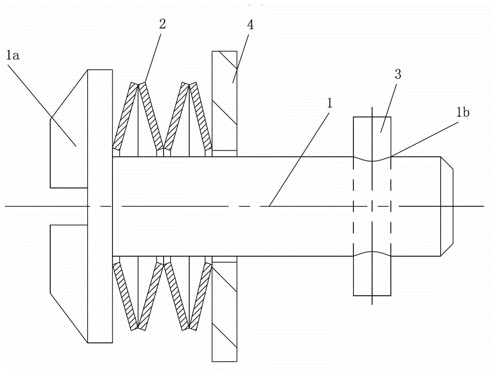
[0030] Such as figure 2 As shown, the connecting rod 1 has an end 1a, the return spring 2 and the flat washer 4 are sequentially sleeved on the connecting rod 1, and the lower end of the connecting rod 1 is provided with a pin through hole 1b, and the limit pin 3 is inserted through the pin. The hole 1b is fixedly connected with the connecting rod 1. The return spring 2 and the flat pad 4 are located between the end 1a of the connecting rod 1 and the pin through hole 1b. The axis of the pin through hole 1b intersects the ...


PUM


Abstract

The invention discloses a stamping part connecting fastening structure which comprises a first stamping part (5), a second stamping part (6) and a fastening connecting assembly. The fastening connecting assembly is composed of a connecting rod (1) with an end (1a), a return spring (2), a limiting pin (3) and a plain cushion (4). The lower portion of the connecting rod (1) and the limiting pin (3) rotate for a certain angle after penetrating through a via hole (5c) on the first stamping part (5) and a combination hole (6c) on the second stamping part (6), until two ends of the limiting pin (3) are respectively stopped through one of limiting protrusions (6d) so as to limit the continued rotation position of the limiting pin (3). The stamping part connecting fastening structure has the advantages that the stamping part connecting fastening structure is low in manufacturing cost, is assembled and disassembled without using a tool and is convenient and efficient and firm and reliable to connect, and secondary loading and unloading are unaffected completely, and the like.

Description

Technical field [0001] The invention relates to sheet metal parts for vehicles, in particular to an assembly structure of sheet metal parts for vehicles. Background technique [0002] There are a large number of sheet metal parts on motorcycles and automobiles. At present, the connection of these parts usually adopts the method of bolt and nut assembly connection, such as Picture 10 As shown, the two sheet metal parts are respectively provided with bolt through holes, and the bolt 8 passes through the two sheet metal parts and is combined with the nut 7 to fasten the two sheet metal parts together. The main problems are: (1) After the bolts and nuts are removed, the nuts are easy to fall off: (2) Such as Picture 11 As shown, due to the limitation of the installation position, it is often necessary to weld the nut 7 to one of the sheet metal parts. The nut 7 is a projection welded nut, which increases the assembly process; (3) When the bolt is tightened, a pneumatic or electric sl...

Claims


Application Information

Patent Timeline
Patent Type & Authority Applications(China)
IPC IPC(8): F16B19/02F16B21/16
Inventor 黄忱鑫邓泽燕杨育奎
Owner 力帆科技(集团)股份有限公司
Learn More