
Diode artificial circuit model

A technology for simulating circuits and diodes, applied in electrical digital data processing, special data processing applications, instruments, etc., can solve problems such as precision sacrifice, and achieve the effect of improving model accuracy and flexibility

Active Publication Date: 2013-04-24
SHANGHAI HUAHONG GRACE SEMICON MFG CORP
View PDF1 Cites 7 Cited by
  • Summary
  • Abstract
  • Description
  • Claims
  • Application Information

AI Technical Summary

Problems solved by technology

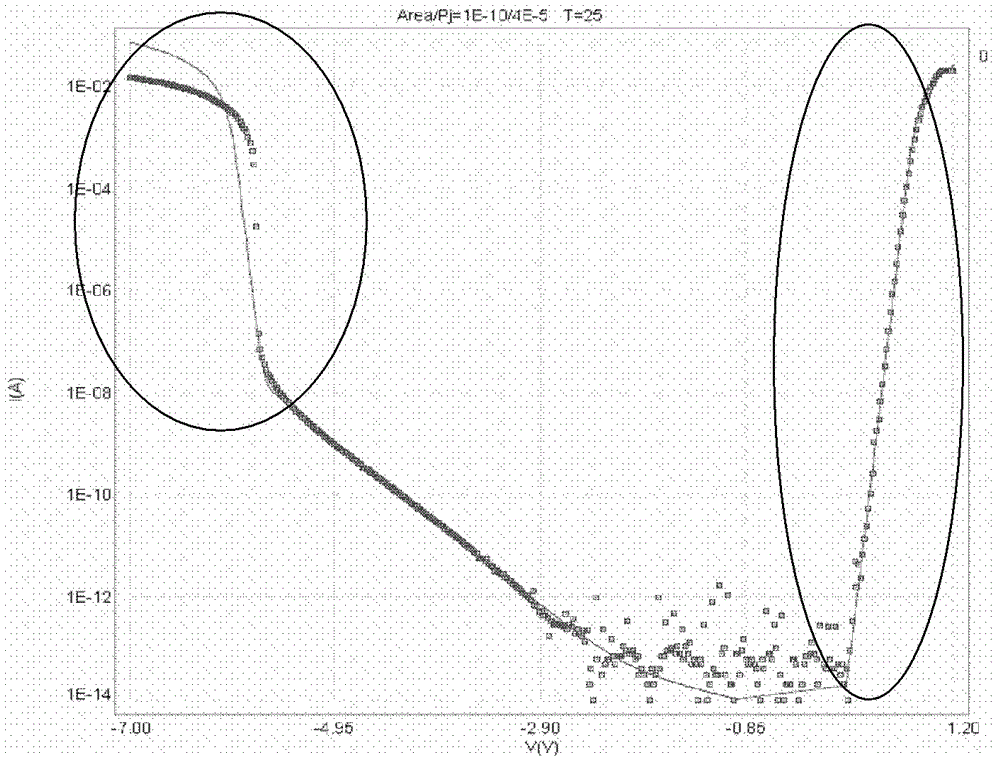
When fitting the model, due to the limitation of the formula, assuming that the Iseff value is fixed, the model can only adjust the slope of the two through the parameter "N", and the result is bound to cause some sacrifices in accuracy.

Method used


Image

  • Diode artificial circuit model
  • Diode artificial circuit model
  • Diode artificial circuit model

Examples


Embodiment Construction

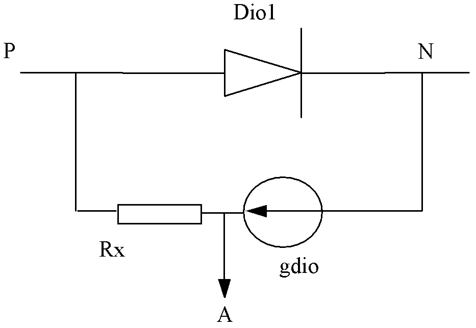
[0025] An embodiment of the diode simulation circuit model of the present invention is as figure 2 As shown, it includes a first forward diode model dio1, a voltage-controlled current source gdio, and a parasitic resistance Rx, and the voltage-controlled current source gdio and the parasitic resistance Rx are connected in series at the P terminal of the forward diode model dio1 and N-terminal;

[0026] For the forward diode model dio1, the reverse breakdown current is zero, and the forward working current is:

[0027] id = ISeff * ( e Vd N * Vt - 1 ) Formula 3;

[0028] Among them, id is the forward working current, ISeff is the effective current coefficient, Vd is the external bias voltage, N is the correction coefficient of the ...


PUM


Abstract

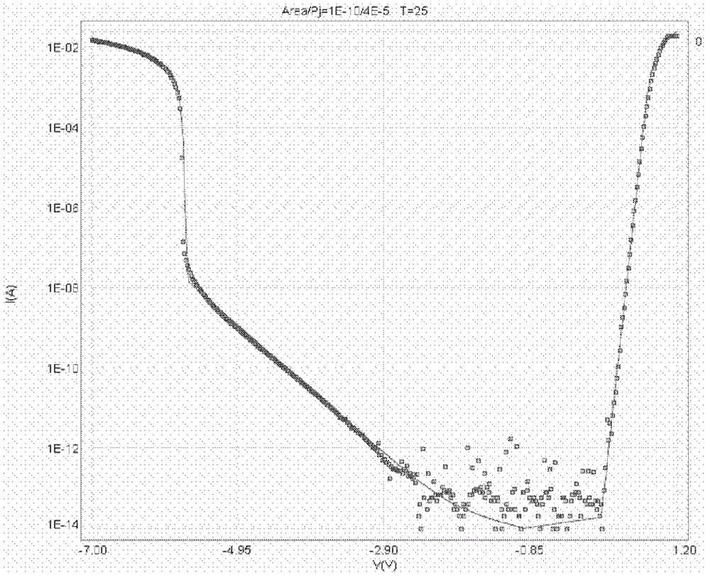
The invention discloses a diode artificial circuit model which comprises a forward direction diode model, and further comprises a voltage-controlled current supply and a parasitic resistor, wherein the voltage-controlled current supply and the parasitic resistor are connected between an end P and an end N of the diode model in series, reverse breakdown current of the forward direction diode model is zero, and the current valve of the voltage-controlled current supply is as follows. According to the diode artificial circuit model, model precision and flexibility of reverse characteristics of the diode are improved, both good registration accuracy of forward working current of the diode and good registration accuracy of backward breakdown current of the diode are achieved.

Description

technical field [0001] The invention relates to semiconductor design technology, in particular to a diode simulation circuit model. Background technique [0002] The HSPICE simulator is recognized as the "gold standard" in the field of accurate circuit simulation, and can provide MOS device model simulation certified by the foundry with the help of first-class simulation and analysis algorithms. It is one of the fastest and most reliable circuit simulators one. [0003] In today's mainstream HSPICE simulator for semiconductor design, the current description formula of the conventional diode (diode) device simulation model is as follows: [0004] The forward working current id of the diode is: [0005] id = ISeff * ( e Vd N * Vt - 1 ) ...

Claims


Application Information

Patent Timeline
Patent Type & Authority Applications(China)
IPC IPC(8): G06F17/50
Inventor 王正楠
Owner SHANGHAI HUAHONG GRACE SEMICON MFG CORP
Learn More