Cable terminal steel pipe pole

A cable terminal and steel pipe rod technology, which is applied to the installation of cables, the spatial arrangement/configuration of cables, electrical components, etc., can solve the problems of difficult to handle the electrical clearance, easy heating of the cable iron, and difficulty in fixing the cable. The effect of saving cable material, saving copper material and simple structure

Inactive Publication Date: 2013-04-24
SHANGHAI INTELLIGENCE POWER ENG CO LTD
View PDF6 Cites 7 Cited by
  • Summary
  • Abstract
  • Description
  • Claims
  • Application Information

AI Technical Summary

Problems solved by technology

When building traditional steel pipe poles with cable terminals, the staff need to install and debug the cable terminals and lightning arresters layer by layer, which is inconvenient for construction and labor-intensive
At the same time, in the later work of cable lead-in corresponding to the cable terminal head and lightning arrester, it also needs to be installed and debugged layer by layer, which is inconvenient for construction and labor-intensive. is longer, such as figure 1 For the traditiona

Method used


Image

  • Cable terminal steel pipe pole
  • Cable terminal steel pipe pole
  • Cable terminal steel pipe pole

Examples


Embodiment Construction

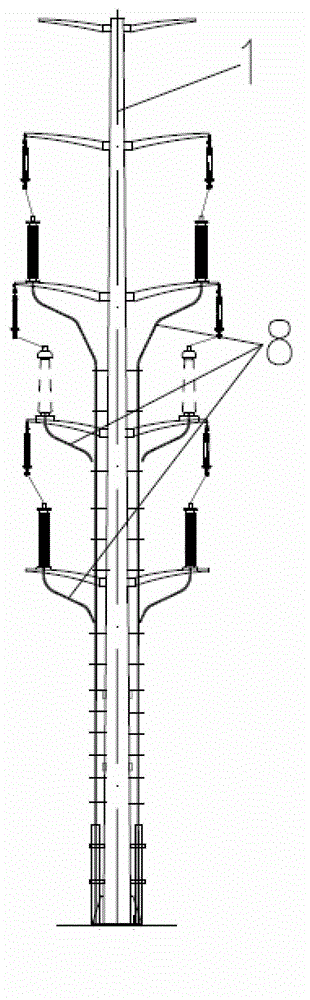
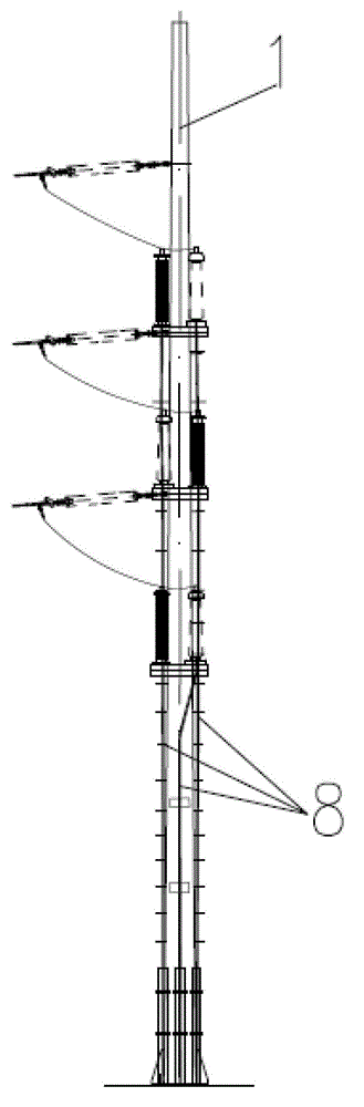
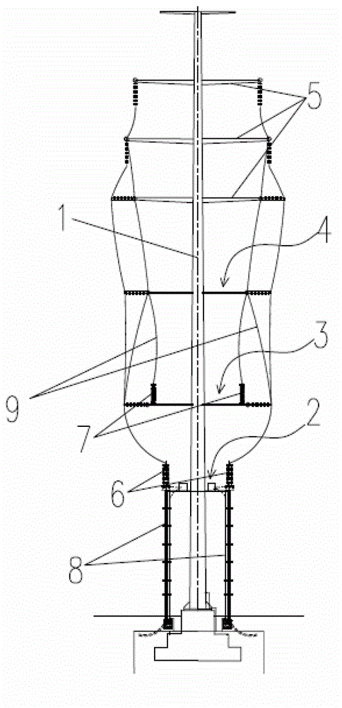
[0021] Such as image 3 and Figure 4 As shown, a steel pipe pole for a cable terminal in this embodiment includes a main pole 1 provided with a crossarm 5, a lightning arrester 7 and a cable terminal head 6, and also includes: a cable terminal bracket layer for centrally arranging the cable terminal head 6 2. The lightning arrester support layer 3 and the silicon rod support layer 4 are used to centrally set the lightning arrester 7, and the cable terminal support layer 2, the lightning arrester support layer 3, the silicon rod support layer 4 and several transverse rods are sequentially arranged on the main pole 1 from bottom to top. The rod 5 and the cable terminal head 6 are arranged on the cable terminal bracket layer 2, and the lightning arrester 7 is arranged on the lightning arrester bracket layer 3.

[0022] Specifically, as shown in the figure, the cable terminal steel pipe pole of this embodiment adopts 3 sets of crossarms 5, 6 cable terminal heads 6 and 6 lightnin...


PUM


Abstract

The invention discloses a cable terminal steel pipe pole which comprises a main pole provided with cross bars, a lightning arrester and a cable terminal joint and further comprises a cable terminal support layer used for concentrated arrangement of cable terminal joint, a lightning arrester support layer used for concentrated arrangement of the lightning arrester and a silicon stick support layer. The main pole is provided with the cable terminal support layer, the lightning arrester support layer, the silicon stick support layer and a plurality of cross bars in sequence from bottom to top. The cable terminal joint is arranged on the cable terminal support layer. The lightning arrester is arranged on the lightning arrester support layer. The cable terminal support layer, the lightning arrester support layer and the silicon stick support layer are additionally arranged on the main pole so that concentrated installation and debugging of the cable terminal joint and the lightning arrestor can be achieved, working intensity of field installation, debugging and overhauling by a worker is reduced greatly, the length of a cable needed is reduced greatly, cost is reduced effectively and copper materials are saved.

Description

technical field [0001] The invention relates to the technical field of electric power facilities, in particular to a steel pipe pole for a cable terminal. Background technique [0002] The steel pipe poles at the cable terminals are usually used to lead the cables to the cross-arm brackets of each layer. The length of the poles on each cable varies greatly, and a lot of precious non-ferrous metals (copper) will be consumed in vain. Since my country's copper reserves are not large, and copper is a valuable national defense material, most of it can only be imported, so it is very meaningful to save copper. [0003] figure 1 and figure 2 Shows the basic structure of a traditional cable terminal steel pipe pole. When building traditional steel pipe poles for cable terminals, workers need to install and debug cable terminals and lightning arresters layer by layer, which is inconvenient for construction and labor-intensive. At the same time, in the later work of cable lead-in...

Claims


Application Information

Patent Timeline
IPC IPC(8): H02G7/20H02G13/00
Inventor 廖昌碧
Owner SHANGHAI INTELLIGENCE POWER ENG CO LTD
Why Eureka
Try Eureka