
Flexible reactive compensation device

A compensation device and flexible technology, applied in the field of power distribution and transformation, can solve problems such as power supply reliability, power quality problems, transmission efficiency, damage to electrical equipment and system stability, and system reverse reactive power, so as to enhance system voltage stability performance, improving effective transmission capacity, and damping system oscillation

Inactive Publication Date: 2013-04-24
SHANGHAI MUNICIPAL ELECTRIC POWER CO +2
View PDF4 Cites 1 Cited by
  • Summary
  • Abstract
  • Description
  • Claims
  • Application Information

AI Technical Summary

Problems solved by technology

The widespread problems in the power distribution system are power supply reliability, power quality problems and transmission efficiency problems.
[0003] In the regional power grid, the reactive power of the system is generally compensated and the power factor is improved by adopting the method of graded switching capacitor banks. This method can only provide capacitive reactive power to the system, and cannot realize fast and accurate adjustment with the change of the load. While ensuring the power factor of the busbar, it is easy to cause reactive power to be sent back to the system, raise the busbar voltage, and endanger the stability of electrical equipment and the system

Method used


Image

  • Flexible reactive compensation device

Examples


Embodiment Construction

[0026] The present invention will be described in detail below in conjunction with the accompanying drawings and specific embodiments.

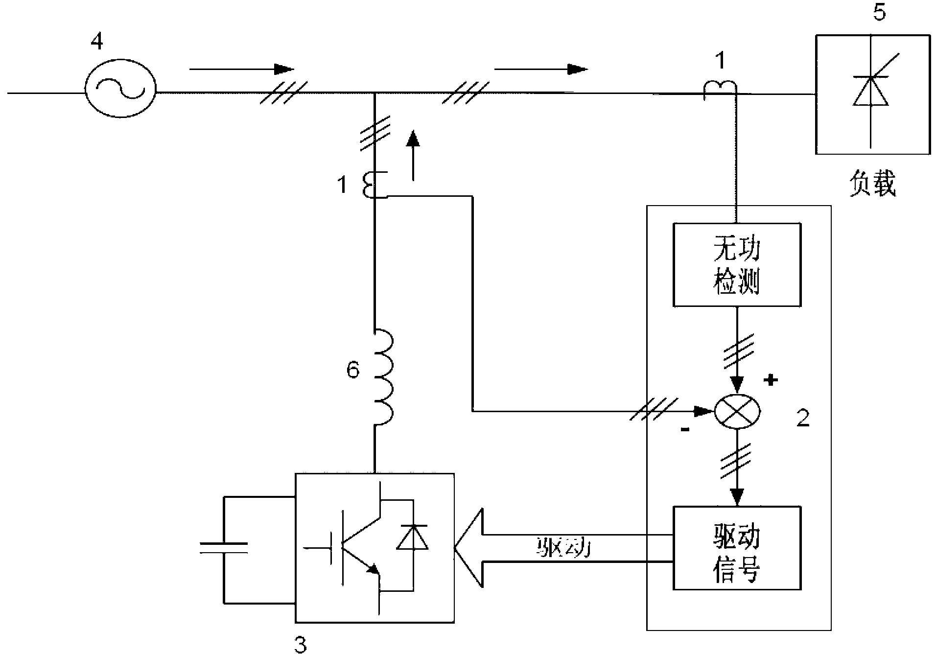
[0027] Example figure 1 As shown, a flexible reactive power compensation device is connected to the AC power grid 4 and includes a reactive power collection module 1, a control module 2 and an inverter module 3, and the reactive power collection module 1 is set on the load side of the AC power grid 5 and the output end of the inverter module 3, the control module 2 is respectively connected to the reactive power acquisition module 1 and the inverter module 3, and the output end of the inverter module 3 is connected to the AC grid 4 through the reactor 6.

[0028] The reactive power acquisition module generates sampled digital signals through current transformers and voltage transformers, and generates corresponding reactive power through calculation, which is finally input into the control module for processing. The control module is realize...


PUM


Abstract

The invention relates to a flexible reactive compensation device which is connected on an alternating current power network and comprises systematic reactive power acquisition modules, a control module and a reactive power inversion module. The reactive power acquisition modules are arranged on the load side of the alternating current power network and at the output end of the inversion module. The control module is respectively connected with the reactive power module and the inversion module. The output end of the inversion module is accessed to the alternating current power network through an electric reactor. Compared with the prior art, the flexible reactive compensation device not only can send out systematic reactive power or absorb the reactive power, improve a power factor, reduce line losses, and save energy and reduce consumption, but also can restrain voltage fluctuation and flickering. Moreover, negative-sequence current caused by an unbalanced load can be quickly compensated so that the balance of three-phase current flowing into the power network can be always guaranteed, and power quality of power supply and consumption is greatly improved.

Description

technical field [0001] The invention relates to power distribution and transformation technology, in particular to a flexible reactive power compensation device. Background technique [0002] my country's power grids are mainly distinguished by voltage levels, of which 66kV / 110kV is called a high-voltage power distribution system, 20kV / 10kV / 6kV is a medium-voltage power distribution system, and 220V / 380V is a low-voltage power distribution system. The widespread problems in power distribution system are power supply reliability, power quality problem and transmission efficiency problem. The transmission efficiency refers to the ratio of the electric energy delivered to the user by the distribution system to the electric energy obtained from the transmission network. Transmission efficiency is related to many factors, one of which is reactive power compensation. When the alternating current passes through the actual load, because it cannot be purely capacitive or purely ind...

Claims


Application Information

Patent Timeline
IPC IPC(8): H02J3/18H02J3/26
CPCY02E40/50Y02E40/30
Inventor 陈勇盛连军苏国豪吴家华张建兴包虎平
Owner SHANGHAI MUNICIPAL ELECTRIC POWER CO
Learn More