Broad-speed-range generator variations

a generator and wide-speed range technology, applied in the direction of electric generator control, motor/generator/converter stopper, dynamo-electric converter control, etc., can solve the problems of high inductance and high loss of iron cores of induction machines, and it is not feasible to use a series low-loss ferrite core inductor with relatively low high-frequency loss, and improve global economies. , the effect of cost-effectiveness

Inactive Publication Date: 2012-10-11
FRADELLA RICHARD B
View PDF5 Cites 55 Cited by
  • Summary
  • Abstract
  • Description
  • Claims
  • Application Information

AI Technical Summary

Benefits of technology

[0028]More cost-effective generators that can produce higher energy yields from variable speed and torque rotary power from wind turbines can help to solve critical global energy needs and environmental problems, and improve

Problems solved by technology

Widely used induction generators, intended to augment grid power by their 3-phase power connections to utility power grids through switch-gear, must presently be limited, because their power disruptions may cause grid failures.
However, induction machines have high inductance and high-loss iron cores, so it is not feasible to use a series low-loss ferrite core inductor having relatively low high-frequency losses, as described for the present invention.
Induction machine core loss would be very high, with attendant heating problems, if subjected to high-frequency switch-mode pulse-width-modulation (PWM) to provide variable-frequency poly-phase sinusoidal voltages having low harmonic distortion across the induction machine stator winding terminals.
But it has substantial harmonic distortion.
The harmonics cause high induction machine losses.
However, such systems are lossy and not self-starting, and require DC power bus storage.
Cogging torque (wherein the rotor angle aligns its iron core poles and holds minimum magnetic reluctance positions), like stiction and friction in gears, may cause wind turbines to stall at low wind speeds.
These shortcomings and too low output voltage at low shaft speeds prevent usable power generation at low wind speeds from this prior art machine.
However, the boost regulator incurs tandem losses, and machine cogging may stall the wind turbine drivin

Method used


Image

  • Broad-speed-range generator variations
  • Broad-speed-range generator variations
  • Broad-speed-range generator variations

Examples


Embodiment Construction

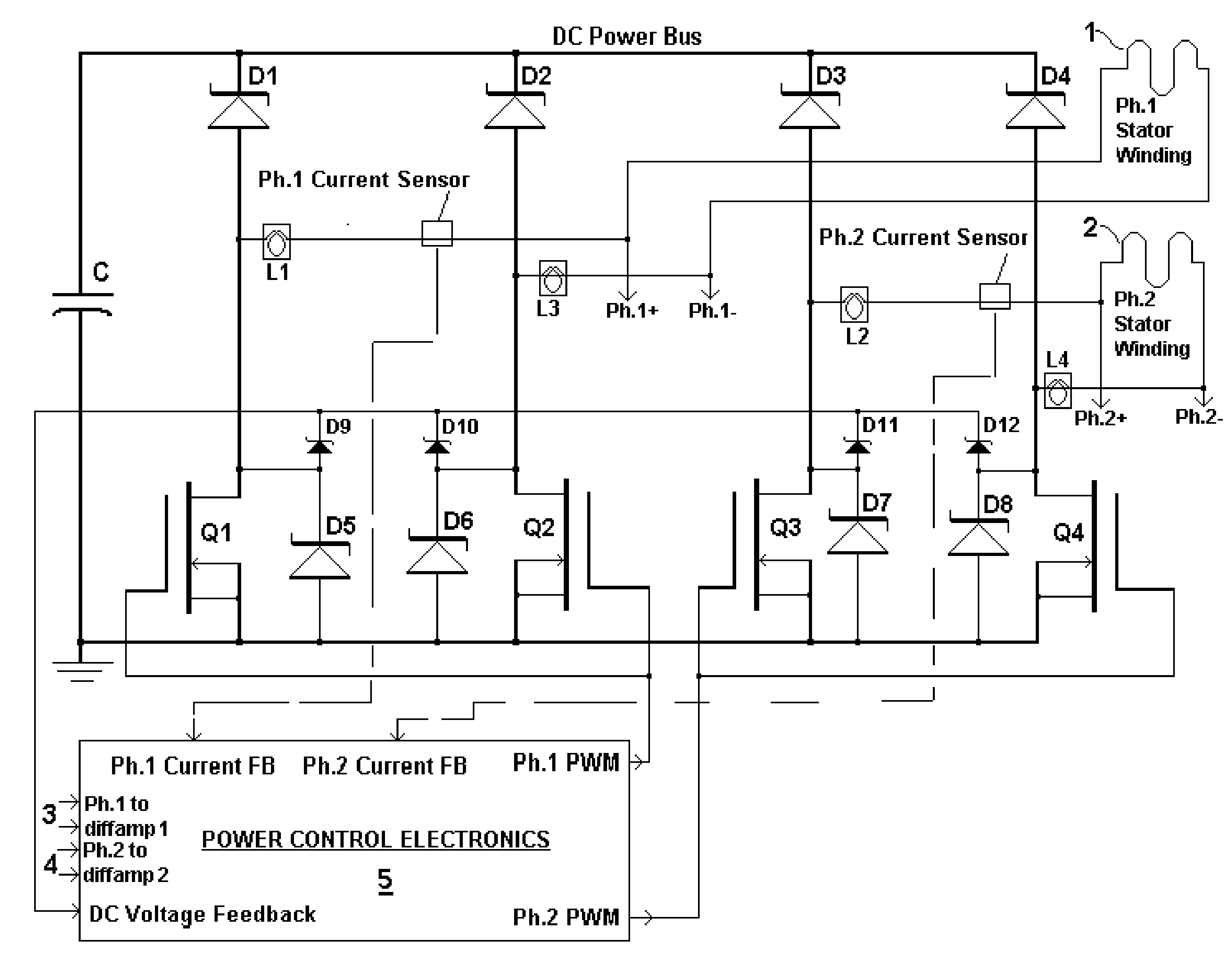
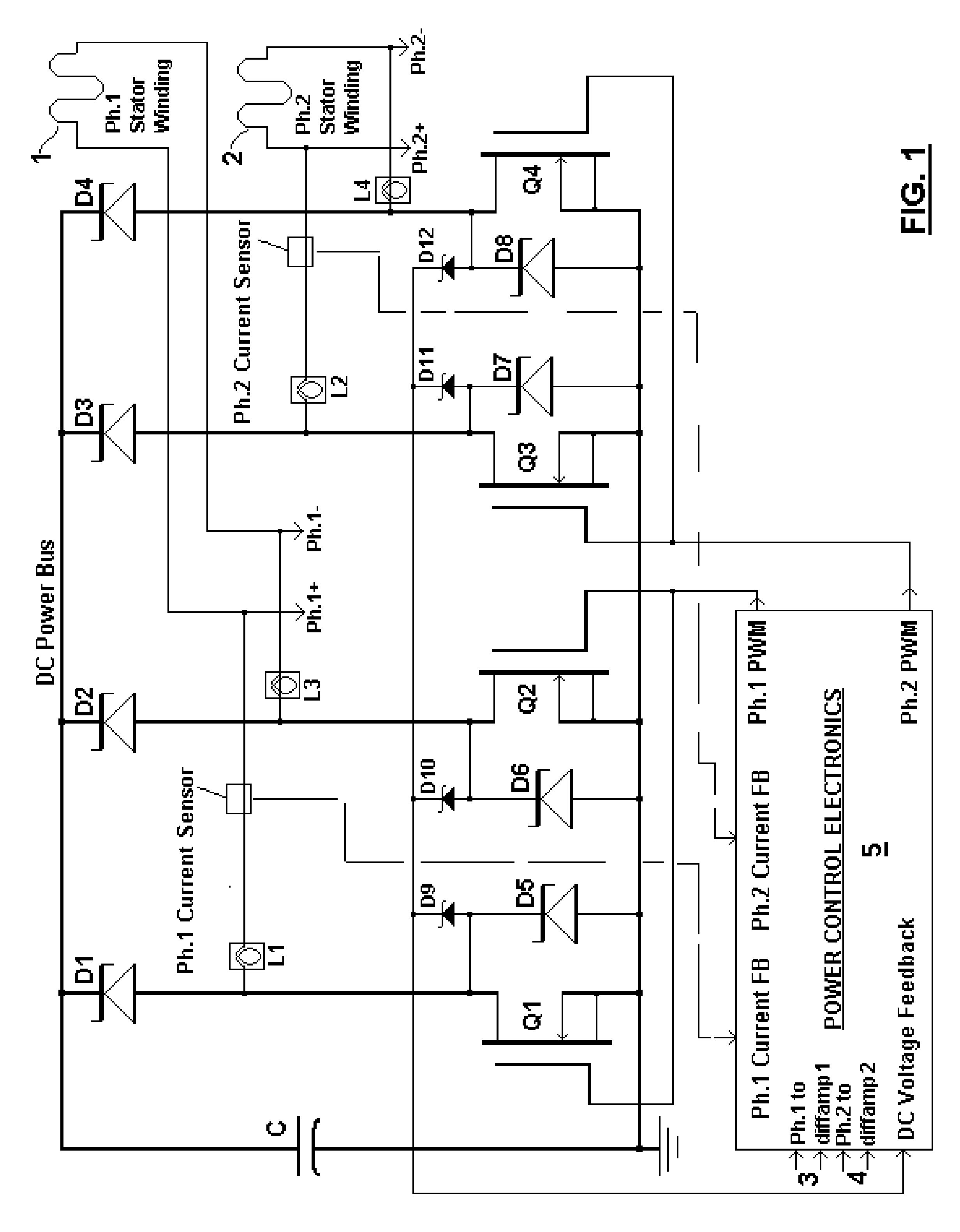
[0063]Main elements and combinations of new generator variations are set forth herein. Integral electronics showing the main circuit variations are illustrated in FIG. 1. Features taught in prior art, with new differences and improvements facilitated by variations set forth herein, are briefly described, to explain differences and to provide clear comparisons. While dimensions, component values, tolerances and the like are presented throughout this document to facilitate better understanding of the design of the preferred embodiment, it will be understood that other dimensions, tolerances and the like are additionally contemplated and will be clearly apparent to those versed in the appropriate arts and sciences.

[0064]Main elements and combinations of the present invention are set forth herein and illustrated in FIG. 1. The generator system variations described provide unique new combinations of a coreless axial-field generator and cooperative power control electronics having similar...


PUM


Abstract

A brushless generator with permanent-magnet multi-pole rotor disks and stator winding disks in their axial magnetic field includes integral electronics to efficiently generate regulated DC current and voltage from mechanical input power over a broad speed range. All power for the electronics is provided by rectifier diodes from its stator windings. Differential amplifiers provide stator voltage feedback signals. Its power rating is scalable, depending on the number of its disks. Having no iron cores and no gears, it incurs no cogging torque, and no gear friction. Integral power control electronics includes high-frequency pulse-width-modulated boost regulation, which provides regulated current at requisite voltage over its broad speed range. A main wind-powered embodiment to produce DC power for a constant voltage DC load over a broad speed range includes signal processing so output power varies according to the third power of speed. Combined boost-regulation, zero cogging torque, and no gearing, enable a wide speed range, for better power quality and higher wind energy yields.

Description

BACKGROUND OF THE INVENTION[0001]1. Field of the Invention[0002]Applicant sets forth herein a brushless DC (direct-current) generator with permanent-magnet rotor disks and stator winding disks responsive to a rotating axial magnetic field in spaces between the rotor disks, including integral electronics, to efficiently generate DC electric power, at current and voltage regulated by the electronics, from broadly variable speed rotary mechanical drive. The present invention includes further variations of generator embodiments set forth in applicant's U.S. Pat. No. 7,646,178 for a “BROAD-SPEED-RANGE GENERATOR”. Said variations are intended to reduce the number of parts needed, and thereby improve reliability, reduce power needed for the integral electronics, reduce the number of conductors between the generator assembly and its power interface electronics, and prevent the generator from drawing power from its DC load without need for electric or electronic parts between the generator a...

Claims


Application Information

Patent Timeline
IPC IPC(8): F03D9/00F03G5/06H02K7/102F03B13/08H02P9/48H02K9/22
CPCH02K1/2793H02K3/47Y02E10/725H02K7/1838H02K21/24H02K7/183Y02E10/72H02K1/2796
Inventor FRADELLA, RICHARD B.
Owner FRADELLA RICHARD B
Why Eureka
Try Eureka