Electrode and method for manufacturing an electrode

a manufacturing method and electrode technology, applied in the field of electrodes, can solve the problems of not being able to prevent the negative effect of the electrode structure during shaping, and the so as to achieve long-lasting and reliable electrode operation, high energy yield, and the effect of reducing the negative influence of the later operation or the possible performance of the electrod

Inactive Publication Date: 2014-09-25
ROBERT BOSCH GMBH
View PDF1 Cites 0 Cited by
  • Summary
  • Abstract
  • Description
  • Claims
  • Application Information

AI Technical Summary

Benefits of technology

[0017]In this context, the above-described method may have, in particular, the advantages, that the disadvantages or the risks, which are involved when shaping, e.g., cutting, the coated current collector for later operation, may be reduced or completely eliminated.
[0018]Specifically, the above-described method may prevent burrs from cutting or stamping being formed, which could have a negative influence on the later operation or the possible performance of the electrode. In addition, particles, which may separate from the active material layer during shaping, may be prevented from causing a short circuit in the cell at an unwanted location during later operation, and from damaging or destroying it in this manner. On the contrary, the present invention may allow particularly long-lasting and reliable operation of an electrode.
[0019]Furthermore, after coating the current collector, a sturdy electrode may be obtained, in which the active material layer or regions of it do not flake off as a result of mechanical loading from stamping; or, for instance, in the case of laser cutting, deformation does not occur at the edge region of the electrode or the material, or the electrode composition does not change due to a high energy yield caused by the laser. Since such effects, as described above, are unwanted in electrodes, cutting waste of the coated material of the related art is often produced. However, such cutting waste may be prevented by the present invention, which may reduce the process costs due to, in particular, the high material costs within the value-added chain of the battery costs, and in this manner, may allow particularly cost-effective manufacturing.
[0020]In addition, a particularly defined embodiment may be produced without negative influences that reduce performance, which means that the performance data may be developed to be particularly high and defined.
[0021]In summary, it consequently allows the above-described method to produce electrodes particularly cost-effectively, precisely, and with a high performance grade of the electrodes to be operated later.
[0022]Within the scope of one embodiment, a current collector foil may be used as a current collector. In this context, a current collector foil may have, in particular, a low thickness with respect to the length and width, and in the process, it may be designed to be approximately foil-like, and thus, particularly flexible. The above-described method may be especially suitable for, in particular, foil-type current collectors or for current collector foils, since in the case of foil-type current collectors, in particular, a negative effect on the electrode structure may not always be able to be completely prevented during shaping. Therefore, current collector foils, in particular, require an especially gentle manufacturing method, in order to be able to produce a waste-free, defined structure. Non-limiting thicknesses of current collector foils, which may be formed from aluminum in the case of a cathode, and from copper in the case of an anode, lie, for example and in a non-limiting manner, in a range of greater than or equal to 5 μm and / or less than or equal to 50 μm. In this context, the thickness of the current collector foils may be selected, in particular, as a function of the desired rigidity of the electrode and / or the rigidity of the active material layer, as such. If, for example, the active material layer has a sufficient rigidity, the thickness of the current collector foils may be selected to be correspondingly low. If, however, the active material or the active material layer does not have sufficient rigidity in itself, a greater thickness of the current collector may be advantageous.

Problems solved by technology

Specifically, the above-described method may prevent burrs from cutting or stamping being formed, which could have a negative influence on the later operation or the possible performance of the electrode.
Since such effects, as described above, are unwanted in electrodes, cutting waste of the coated material of the related art is often produced.
The above-described method may be especially suitable for, in particular, foil-type current collectors or for current collector foils, since in the case of foil-type current collectors, in particular, a negative effect on the electrode structure may not always be able to be completely prevented during shaping.

Method used


Image

  • Electrode and method for manufacturing an electrode
  • Electrode and method for manufacturing an electrode

Examples


Embodiment Construction

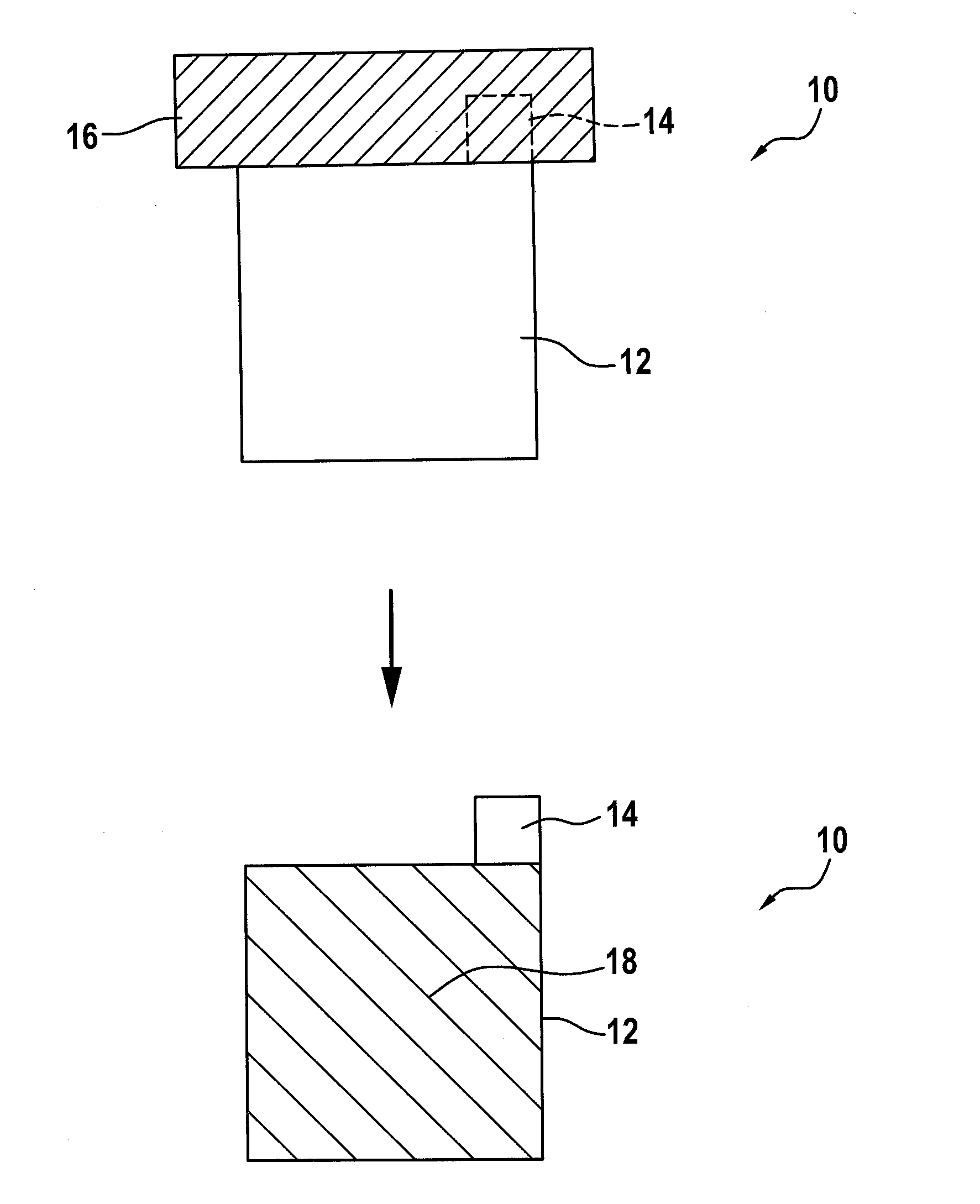
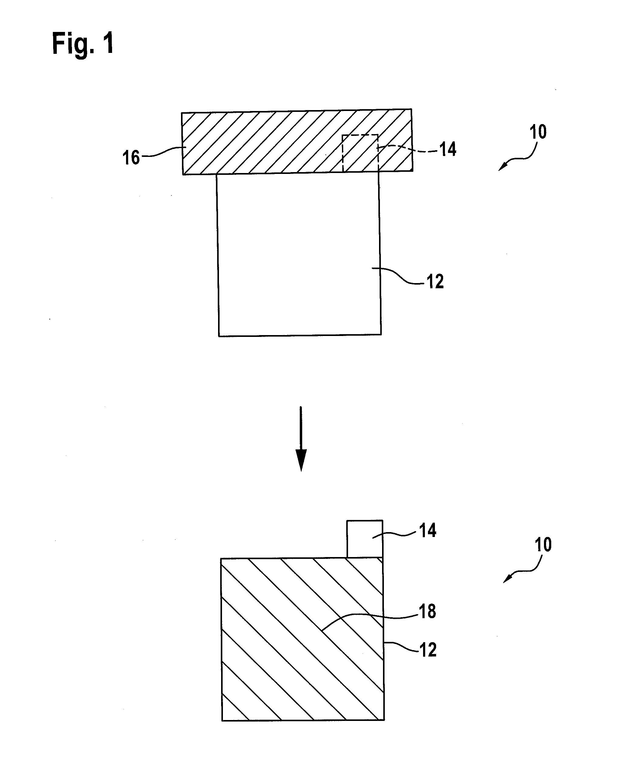
[0032]A method step for manufacturing an electrode 10 is shown in FIG. 1. In particular, the step of coating current collector 12 with an active material mixture is shown in FIG. 1. Such an electrode 10 may be part of a lithium ion battery, for example, and may be used, as such, in both consumer electronics and electrically powered vehicles.

[0033]In this context, it is apparent from FIG. 1 that current collector 12, which may be, for instance, a current collector foil, may be preformed, in particular, prior to applying the active material mixture, by cutting or stamping, for instance. Furthermore, a current pick-up 14, such as a current pick-up flag, may be positioned on current collector 12.

[0034]In this context, shown in FIG. 1 is the application of the, in particular, solvent-containing, active material mixture to at least a partial region of current collector 12, to form an active material layer 18. This may be carried out, using screen printing, printing, spraying, or using a s...


PUM

PropertyMeasurementUnit
currentaaaaaaaaaa
porosityaaaaaaaaaa
concentrationaaaaaaaaaa

Abstract

A method for manufacturing an electrode, including the following method steps: providing an active material mixture containing solvent; providing a preformed current collector; applying the solvent-containing, active material mixture to at least a partial region of the current collector to form an active material layer; and drying the active material layer. Such a method provides a particularly cost-effective manner of being able to manufacture an electrode without waste. Also described is an electrode.

Description

FIELD OF THE INVENTION[0001]The present invention relates to an electrode. The present invention further relates to a method for manufacturing an electrode.BACKGROUND INFORMATION[0002]In the manufacturing of electrodes, such as foil-type electrodes for, for instance, lithium ion cells, the battery material is often applied to a current collector in the form of a slurry, the current collector being able to be a current collector foil. In this case, the current collector foil is mostly a metallic foil, the metal being selected as a function of the electrode to be manufactured. In this context, the current collector foil may be unrolled from a roll prior to the coating and rolled up again after the coating. In addition, the coated current collector foil is dried, for instance, using convection drying or IR-drying, in which the solvent of the slurry may be expelled. In most cases, calendering is subsequently carried out, in order to adjust the porosity formed, for instance, during dryin...

Claims


Application Information

Patent Timeline
Patent Type & Authority Applications(United States)
IPC IPC(8): H01M4/04H01M4/139H01M4/13
CPCH01M4/0404H01M4/139H01M4/13H01M4/0414H01M4/0471H01M4/70Y02E60/10
Inventor HIPPCHEN, SILVANNETZ, ANDREAS
Owner ROBERT BOSCH GMBH
Why Eureka
Try Eureka