

Exhaust heat recovery system having a working fluid circuit and method for operating such an exhaust heat recovery system
- Summary
- Abstract
- Description
- Claims
- Application Information
AI Technical Summary
Benefits of technology
Problems solved by technology
Method used
Image

Examples
Embodiment Construction
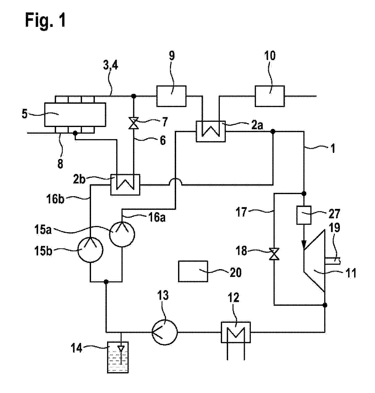
[0032]The exhaust heat recovery system shown diagrammatically in FIG. 1 has a working fluid circuit 1 with a first heat exchanger 2a and a second heat exchanger 2b, wherein in principle only a single heat exchanger or also more than two heat exchangers may be part of the exhaust heat recovery system. The heat exchangers 2a, 2b are configured as or function as evaporators, and on an internal combustion engine 5, are adapted for recovery of the waste heat generated in operation of the internal combustion engine 5. An exhaust gas stream 4 from the internal combustion engine 5, which is guided in an exhaust gas line 3 of the internal combustion engine and forms a waste heat stream, flows through the first heat exchanger 2a. In addition to the first heat exchanger 2a, the second heat exchanger 2b is installed in a line in the form of an exhaust gas recirculation line 6 or other heat transfer line. Via the exhaust gas recirculation line 6, a partial quantity of exhaust gas is taken from t...
PUM
 Abstract
Description
Claims
Application Information