
Power generation device for a vehicle

Inactive Publication Date: 2017-10-26
WEIDPLAS
View PDF23 Cites 1 Cited by
  • Summary
  • Abstract
  • Description
  • Claims
  • Application Information

AI Technical Summary

Benefits of technology

The patent describes an electric power generating device that can be used in a variety of vehicles to convert vibrations into electrical energy. The device has a sensor that can detect the vibrations of the vehicle and adjust the resonant frequency of the oscillation system accordingly. This allows for optimal adjustment of the oscillation system to the vehicle's current conditions, without the need for manual adjustments. The device can be retrofitted to existing vehicles, reducing production costs. It has a slim design, making it space-saving in vehicles. The device can also have multiple oscillation systems with different resonant frequencies to account for different vibration frequencies. The sensor can be placed on the electric power generating device or directly on the vehicle to detect the vibrations. The device has an energy storage for storing the electrical energy generated by the induction unit, allowing for continued use even after the vehicle has stopped. The oscillation system is disposed parallel to the direction of motion of the inertial mass, making it space-saving in vehicles.

Problems solved by technology

Usually, in the case of such trim strips, the amount of energy required for backlighting is very small.
It is precisely in the case of trim strips, and particularly in the case of entry strips, that there is a risk of ingress of moisture into the vehicle in the region of a drilled hole through which the connecting cable is routed.
Moreover, the electrical devices, and particularly entry strips, are frequently exposed to external mechanical influences that may result in the connecting cable connected thereto becoming kinked or pinched, particularly if it is routed through a drilled hole in the body.
In addition, owing to the elaborate cabling, retrofitting vehicles with such electrically operated devices is costly.
The disadvantage of batteries, or storage batteries, is that they have to be replaced, or recharged, after a certain period of time, which means an certain amount of effort on the part of the user.
In addition, the batteries, or storage batteries, are subject to temperature fluctuations, as a result of which their functioning and service life cannot be adequately assured, depending on the particular application and type of application.
However, depending on the vehicle type, charge state, road surface, etc., the energy yield of such autonomous energy supply system is frequently unsatisfactory.

Method used


Image

  • Power generation device for a vehicle
  • Power generation device for a vehicle
  • Power generation device for a vehicle

Examples


Embodiment Construction

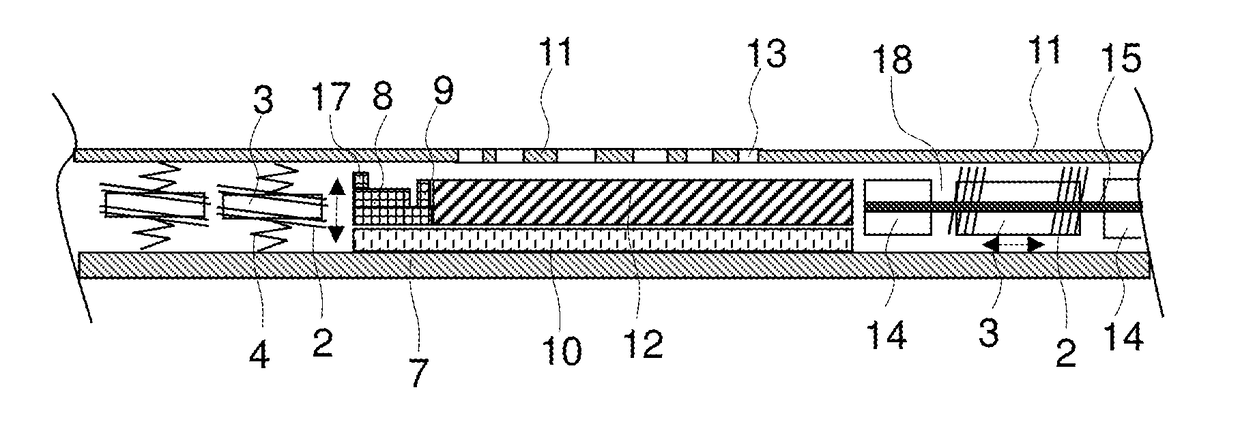
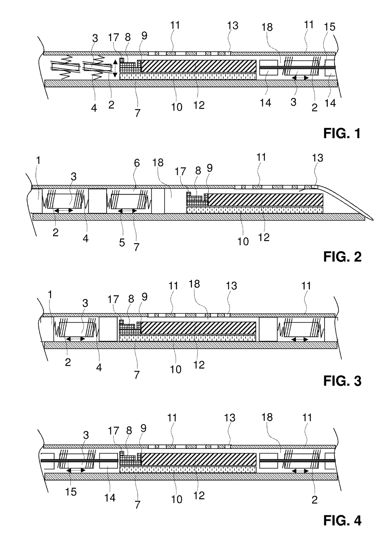
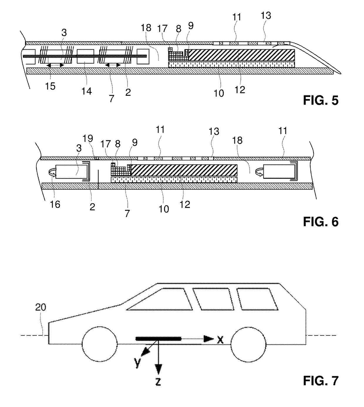
[0043]FIGS. 1 to 6 show differing embodiments of electric power generating devices according to the invention for a vehicle. All of the devices shown in FIGS. 1 to 6 are trim strips that, preferably, are disposed as an entry strip in the foot region of one of the vehicle doors. The trim strips may, however, be disposed at any other location inside or on the outside of the vehicle, such as, for example, in the region of the trunk door or the dashboard. Preferably, the trim strips have a longitudinal direction, defined by the maximum longitudinal extent of the trim strip, that extends parallel to the longitudinal axis 20 of the vehicle. Advantageously, the trim strip is fixedly connected to the vehicle body. In particular, it may be stuck onto a vehicle element that is fixedly connected to the vehicle body, or fastened by means of magnets, i.e. indirectly fastened to the vehicle body, or directly fastened to the vehicle body.

[0044]In respect of the embodiments shown in FIGS. 1 to 6, r...


PUM


Abstract

Disclosed is a power-generating backlit trim strip for a vehicle, comprising an oscillation system (3, 4; 3, 14), an induction unit (2), a sensor (17) and a control unit (8). The oscillation system (3, 4; 3, 14) includes a movably arranged gyrating mass (3), and the induction unit (2) is used for inductively converting kinetic energy of the gyrating mass (3) into electricity. The sensor (17) is used for determining a frequency of the vehicle vibrations, and the control unit (8) is used for adjusting the resonant frequency of the oscillation system (3, 4; 3, 14) to a determined frequency of the vehicle vibrations.

Description

TECHNICAL FIELD[0001]The present invention relates to an electric power generating device for a vehicle. The device may be a backlightable trim strip, such as, for example, and entry strip. The invention additionally relates to a vehicle having such a device, and to a method for generating electrical energy in a vehicle.PRIOR ART[0002]In vehicles, and particularly in the field of automobiles, it is frequently the case that a multiplicity of different electrically operated devices are used, such as, for example, a car radio, a hands-free car kit, an air-conditioning system, etc. These devices usually draw the energy required for their operation from the vehicle's electrical system, which usually has an energy storage in the form of a storage battery, which is itself charged by the engine during travel.[0003]Besides these devices that have a relatively high energy demand, ever more frequently in vehicles electrically operated devices are used that have a comparatively low demand for e...

Claims


Application Information

Patent Timeline
IPC IPC(8): H02K7/18H01L41/113H02N1/08H02K35/04B60G17/019B60Q1/32
CPCH02K7/1892H01L41/113B60G17/01908H02N1/08B60Q1/323H02K35/04F03G7/08H02J7/14H02K35/02B61D43/00B60L1/14B60Q3/64B60Q3/217B60Q3/80H02J7/345H02J50/001H02J50/00Y02T10/64Y02T30/00Y02T10/90H10N30/30
Inventor BUEHRLE, SASCHABODMER, URS
Owner WEIDPLAS
Learn More