
AP (access point) transmitting power optimization method based on energy conservation and interference avoidance in green WLAN (wireless local area network)

A transmission power and optimization method technology, applied in power management, energy-saving ICT, energy consumption reduction, etc., can solve problems such as mutual interference of AP co-frequency components, energy waste, affecting communication quality, etc., to reduce and co-frequency interference, reduce The effect of energy expenditure

Active Publication Date: 2013-04-24
HARBIN INST OF TECH
View PDF3 Cites 38 Cited by
  • Summary
  • Abstract
  • Description
  • Claims
  • Application Information

AI Technical Summary

Problems solved by technology

[0009] The present invention aims to solve the problem of energy waste caused by the dense deployment of APs and overlapping coverage areas in the WLAN environment, and the mutual interference of the same-frequency components of the multiplexed APs during communication, which affects the communication quality.

Method used


Image

  • AP (access point) transmitting power optimization method based on energy conservation and interference avoidance in green WLAN (wireless local area network)
  • AP (access point) transmitting power optimization method based on energy conservation and interference avoidance in green WLAN (wireless local area network)
  • AP (access point) transmitting power optimization method based on energy conservation and interference avoidance in green WLAN (wireless local area network)

Examples


specific Embodiment approach 1

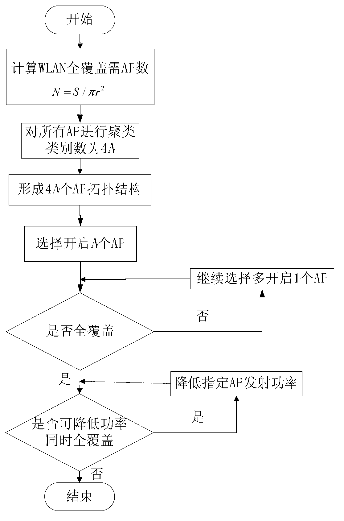
[0038] Specific implementation mode one: as figure 1 As shown, the AP transmission power optimization method based on energy saving and interference avoidance in the green WLAN described in this embodiment is carried out for APs that have been densely deployed in the WLAN, and it includes the following steps:

[0039]1. Determine the number of APs N required for full coverage of the WLAN, that is, divide the total area of ​​the WLAN area by the individual coverage area of ​​each AP, and round up to get an integer N; this is an ideal value. In fact, there will be many overlapping coverages between APs. In the area, in order to ensure full coverage, set the required number of APs to 4N, and then consider appropriately reducing the number of enabled APs;

[0040] 2. Establish a two-dimensional Cartesian coordinate system, and use a clustering algorithm to cluster the densely deployed APs in the WLAN according to their geographical locations. The target is 4N categories; then, in ...

specific Embodiment approach 2

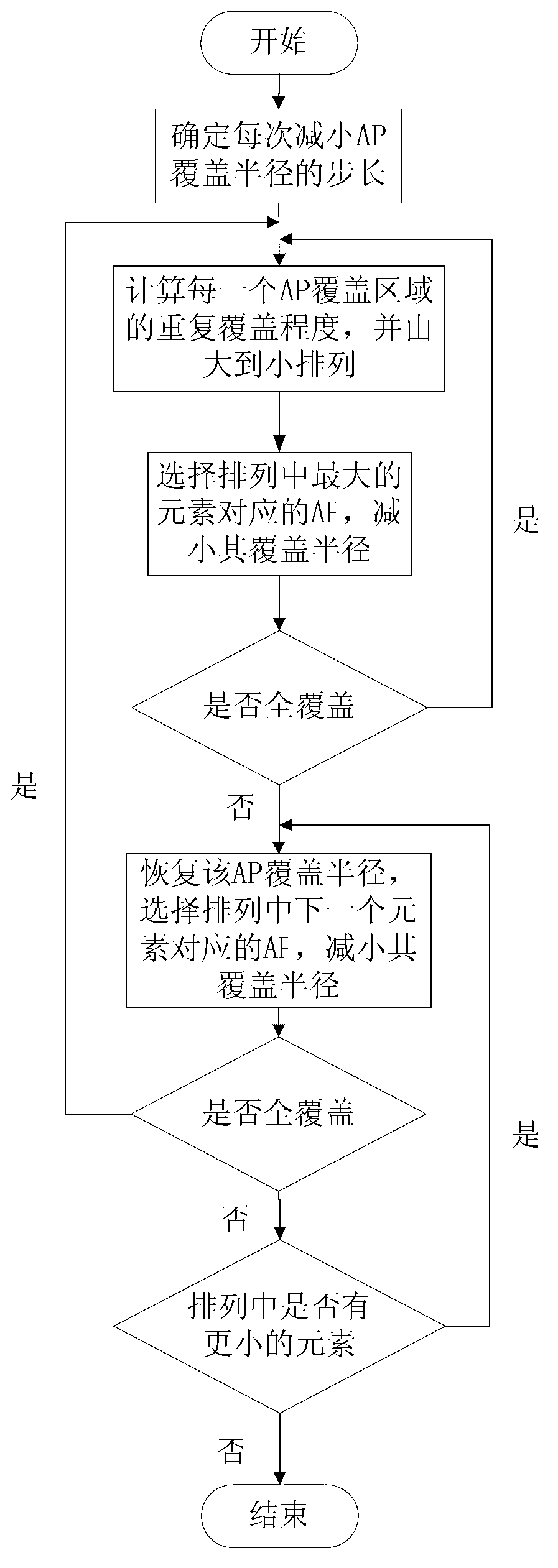
[0044] Specific implementation mode two: as figure 2 As shown, this implementation mode is a further limitation to the specific implementation mode 1:

[0045] AP transmit power optimization method implementation process: This process performs transmit power optimization control based on energy saving and interference avoidance for APs whose positions and numbers have been fixed in the WLAN. Relationship to coverage radius:

[0046] Channel transmission loss satisfies formula (1):

[0047] L(d)=|d| -n S(d)R(d)(1)

[0048] In formula (1), d is the transmission distance, |d| -n is the path loss, n is a constant between 3 and 6, S(d) represents shadow fading, and R(d) represents multipath fading. It can be seen that the farther the transmission distance is, the greater the fading is;

[0049] The received power satisfies formula (2):

[0050] P r (dBm) = P t (dBm)+G t (dB)+G r (dB)+L(dB)(2)

[0051] In formula (2), P r Indicates the received power, P t Indicates th...

specific Embodiment approach 3

[0073] Here is an example for analysis:

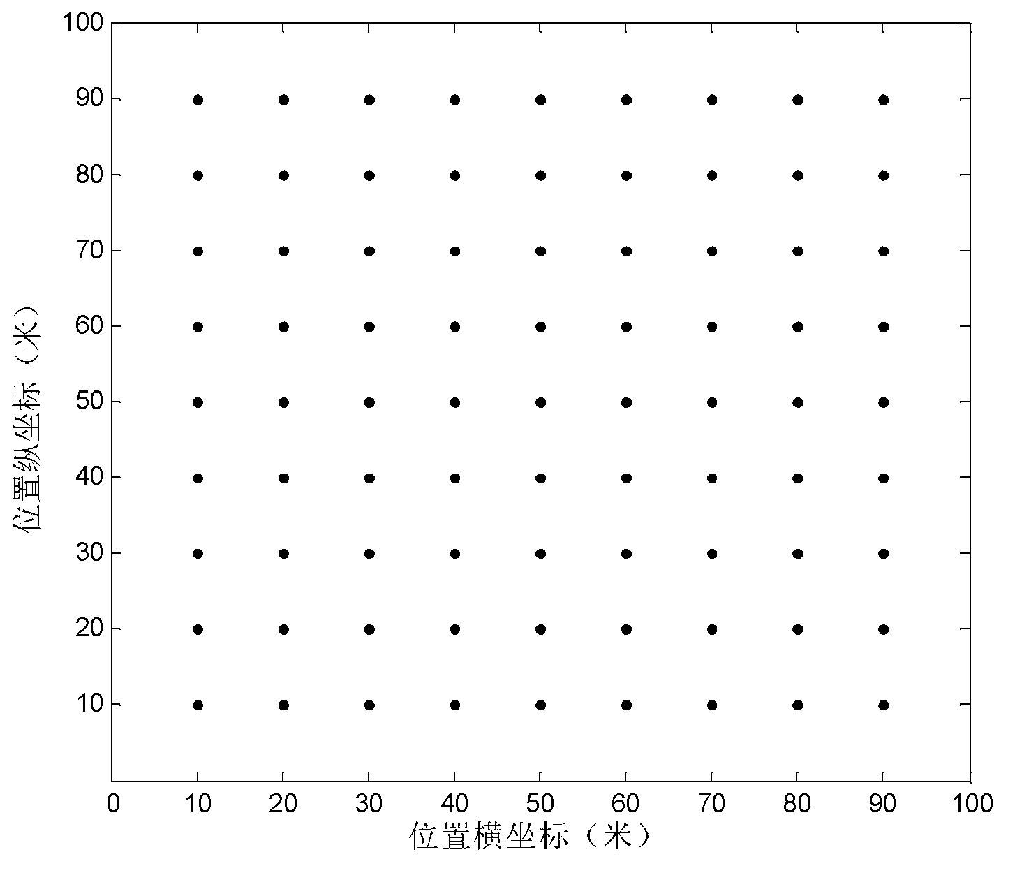
[0074] The schematic diagram of the WLAN environment is as follows: image 3 As shown, the wireless coverage area is 100m×100m, and 81 APs are evenly distributed inside. Take the initial AP coverage radius as: r=30m.

[0075] When each AP is turned on individually, the coverage area is: S cover = πr 2

[0076] Total coverage area of ​​WLAN experimental scenarios: S total =100×100=10000m 2

[0077] Theoretically, the number of APs required to complete full coverage is:

[0078] In order to ensure full coverage, the number of initially selected cluster center APs is: 4N=16.

[0079] According to the geographic location, 81 APs are clustered by the fuzzy K-means clustering algorithm, and 4N results and corresponding central node AP coordinates are obtained. According to the "minimum-maximum principle", when the number of enabled APs is 9, full coverage is satisfied, and the following is obtained: Figure 4 The schematic diagra...


PUM


Abstract

The invention relates to an AP (access point) transmitting power optimization method based on energy conservation and interference avoidance in a green WLAN (wireless local area network). The AP transmitting power optimization method is used for solving the problems of energy waste caused by the dense deployment of APs and the superposition of coverage areas, and the influence of common-frequency components on the communication quality in the WLAN. The AP transmitting power optimization method comprises the following steps of: determining the number of the APs required to be used for realizing WLAN full coverage according to the WLAN and the coverage range of a single AP with default transmitting power; clustering the APs with the dense deployment in the WLAN by adopting a fuzzy K-mean clustering method or a neural network method or other methods; selectively closing the majority of APs according to a clustering result, realizing WLAN wireless signal full coverage by the remainder minority of the APs, and forming an AP distribution structure simultaneously, namely, initializing an AP transmitting power optimization algorithm; repeatedly calculating the repeated coverage degree of each AP coverage area, and arraying the coverage areas; and controlling the AP transmitting power to reduce the coverage radius of each AP, so as to realize the purposes of energy conservation and interference avoidance of the APs.

Description

technical field [0001] The invention relates to a wireless access point AP (Access Point) transmission power optimization method for energy saving and environmental protection and reducing co-frequency component interference in a green wireless local area network WLAN (Wireless Local Area Network), and relates to the WLAN technical field. Background technique [0002] The WLAN technology developed at the end of the 20th century is the product of the combination of computer network and wireless communication technology. It uses radio frequency transmission technology to transmit data and provide users with wireless broadband access services. WLAN does not require wiring, greatly reduces network costs, and has strong mobility. These advantages make WLAN widely popular. More and more offices, schools, families, etc. start to use WLAN. [0003] While WLAN provides convenient communication, it also brings energy consumption problems that cannot be ignored. Green WLAN adheres to ...

Claims


Application Information

Patent Timeline
IPC IPC(8): H04W52/02H04W52/18
CPCY02B60/50Y02D30/70
Inventor 马琳郑秀明徐玉滨卢洋莫云夏颖谭学治
Owner HARBIN INST OF TECH
Learn More