System with valve device for a pneumatically operated brake system, valve device, brake actuation device, trailer control valve device, and device for controlling for the system, brake system, vehicle, use of a component, and method for retrofitting

A technology of brake equipment and brake control, which is applied in the system field of valve devices, and can solve the problems of initial equipment and modification costs

Active Publication Date: 2013-04-24
ZF CV SYST EURO BV
View PDF5 Cites 17 Cited by
  • Summary
  • Abstract
  • Description
  • Claims
  • Application Information

AI Technical Summary

Problems solved by technology

This makes both initial equipment and retrofitting of the vehicle costly
It is particularly complex to convert a vehicle with EBS brake system into a vehicle with ABS brake system (without EBS) or a purely pneumatic brake system (without ABS)

Method used


Image

  • System with valve device for a pneumatically operated brake system, valve device, brake actuation device, trailer control valve device, and device for controlling for the system, brake system, vehicle, use of a component, and method for retrofitting
  • System with valve device for a pneumatically operated brake system, valve device, brake actuation device, trailer control valve device, and device for controlling for the system, brake system, vehicle, use of a component, and method for retrofitting
  • System with valve device for a pneumatically operated brake system, valve device, brake actuation device, trailer control valve device, and device for controlling for the system, brake system, vehicle, use of a component, and method for retrofitting

Examples


Embodiment Construction

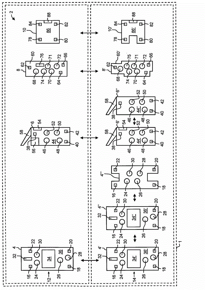
[0056] figure 1 A system 1 for a pneumatic braking device is shown. The system 1 is designed modularly, in particular as a modular system, and has a plurality of replacement components 2 . The replacement component 2 is a valve device 4 , a brake actuating device 6 , a trailer control valve device 8 and a device 10 for control. From these replacement components 2 , the system each has at least one first variant 12 and at least one second variant 14 . The first and second variants 12 and 14 of each replacement component 2 can each alternatively be installed or installed in the brake system.

[0057] For example, the brake system can initially have all replacement components 2 in the form of the first variant 12 . All or individual replacement components 2 can, for example, be replaced by a respective second variant 14 of the respective replacement component 2 for a changeover of the brake system. The replacement of identically or identically configured variants 12 or 14 wit...


PUM


Abstract

The invention relates to a system (1) having at least one valve device (4, 4', 4'', 4''') for a pneumatically operated brake system (90, 90') of a vehicle, wherein the brake system (90, 90') has the valve device (4, 4', 4'', 4''') and at least one brake (92, 94, 98, 100). By means of the valve device (4, 4', 4'', 4''') a pneumatic brake pressure which can be fed to the brake is adjusted in a controlled manner. According to the invention, the system has at least two variants (12, 14) of the valve device (4, 4', 4'', 4''') which can be used alternatively in the brake system (90, 90'). Here, a first variant (12) is configured as a modulator for use in an electronically regulated embodiment of the brake system (90), and a second variant (14) is configured for use in a pneumatically controlled embodiment of the brake system (90'). However, both variants (12, 14) of the valve device (4, 4', 4'', 4''') have pneumatic interfaces (24, 26, 28, 30) and mechanical fastening points (16, 18, 20, 22) which are configured identically with respect to one another. Furthermore, the invention relates to the valve device (4, 4', 4'', 4''') for the system (1), and a brake actuation device (6, 6', 6'''), a trailer control valve device (8, 8') and a device for controlling (10, 10') in each case for this system (1). Moreover, the invention relates to a brake system (90, 90') for a vehicle with at least one replacement component (2) of the system (1), to the vehicle, the use of a component of a brake system as component (2) of the system (1), and a method for retrofitting a brake system, in which method a component of the brake system is replaced by a component (2) of the system (1) according to the invention.

Description

technical field [0001] The invention relates to a system with at least one valve arrangement for a pneumatic brake system, eg of a motor vehicle. Such a brake system has a valve arrangement with at least one valve for modulating or boosting the brake pressure and at least one brake, ie usually a brake on each wheel of the vehicle. In response to an actuation of the brake actuating device, for example by means of the foot brake pedal, the pneumatic brake pressure is modulated by means of the valve device and supplied to the brake via a compressed air line or tube. [0002] Furthermore, the invention relates to components of the system, in particular to a brake actuating device, a valve device, a trailer control valve device and an electronic control unit, a brake system, a vehicle and a method for retrofitting a brake system with these components. Background technique [0003] Braking systems are known in various embodiments, namely in one embodiment as a purely pneumatic br...

Claims


Application Information

Patent Timeline
Patent Type & Authority Applications(China)
IPC IPC(8): B60T13/66B60T13/68B60T17/22
CPCB60T13/662B60T17/228B60T13/665B60T13/683B60T13/24
Inventor 伯恩德-约阿希姆·基尔哈特穆特·罗森达尔格德·罗塔斯沃尔夫冈·施特拉赫奥特马尔·施特鲁韦
Owner ZF CV SYST EURO BV
Why Eureka
Try Eureka