
Unbalanced shaft and method for producing same

A balance shaft, balancing technology, used in spring/shock absorber manufacturing, vibration suppression adjustment, springs, etc.

Active Publication Date: 2013-04-24
SCHAEFFLER TECH AG & CO KG
View PDF5 Cites 7 Cited by
  • Summary
  • Abstract
  • Description
  • Claims
  • Application Information

AI Technical Summary

Problems solved by technology

However, this method for engaging the bearing ring on the associated bearing section of the unbalanced shaft can have some disadvantages

Method used


Image

  • Unbalanced shaft and method for producing same
  • Unbalanced shaft and method for producing same
  • Unbalanced shaft and method for producing same

Examples


Embodiment Construction

[0037] Should be attached Picture 12 At the beginning of the description of the present invention, the accompanying drawings combined with a schematic transmission diagram show a mass balance transmission of a reciprocating piston internal combustion engine in the form of a four-cylinder tandem structure, which is also known as Lancaster-Ausgleich. The internal combustion engine 1 includes a piston 2 oscillating in its cylinder, the longitudinal movement of which is converted into the rotation of a crankshaft 4 by a crank 3. This (here via the intermediate shaft 5) drives two unbalanced shafts 6 with an unbalanced 7, wherein the unbalanced shaft 6 is parallel to the crankshaft 4 and rotates in the opposite direction at a doubled crankshaft speed in order to compensate for the second-order free inertia force.

[0038] As explained below, the present invention provides an unbalanced shaft made of cast steel with a support made of hardened rolling bearing steel (such as model 100Cr6...


PUM


Abstract

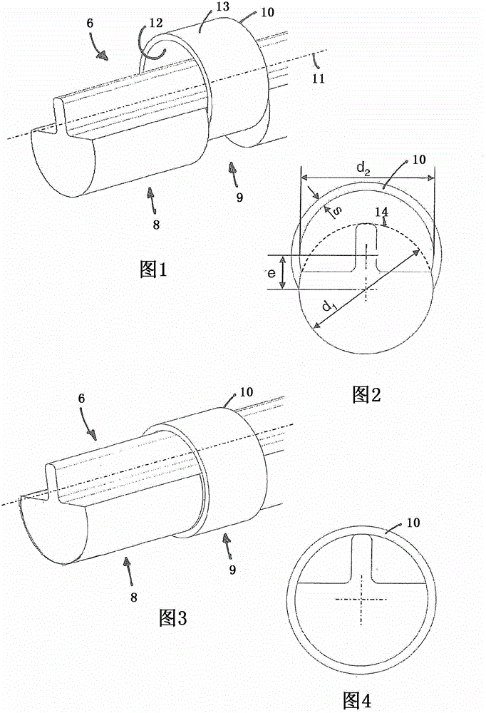
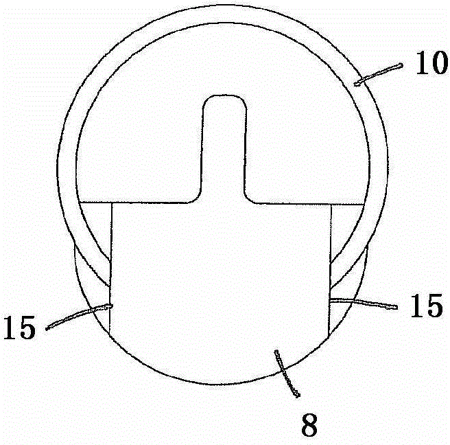
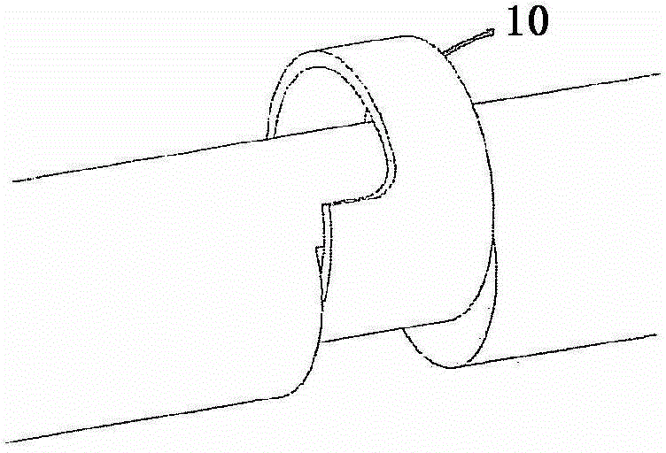
The invention relates to an unbalanced shaft for compensating for mass forces and / or mass moments of an internal combustion engine (1), having an unbalanced segment (8), the center of mass of which extends eccentric to the axis of rotation (11) of the unbalanced shaft (6) for generating the shaft imbalance (7), a bearing segment (9) adjacent to the unbalanced segment, and a bearing race (10) joined thereto, the outer surface (13) of which serves as a race for the rolling elements of a roller bearing rotationally supporting the unbalanced shaft, and the inner surface (12) of which retracts radially relative to the outer circumscribed circle (14) of the unbalanced segment in a bearing circumference region running in the direction of the imbalance. In order to assemble the bearing race on the bearing segment, the following geometric relationships are provided: (i) d2 > d1, (ii) e > 1 / 2 (d2 - d1), (iii) e < 1 / 2 (d2 + d1), where d1 = outer circumscribed circle diameter of the unbalanced segment and the bearing segment, d2 = inner diameter of the bearing race, and e = center point offset between d2 and d1.

Description

Technical field [0001] The invention relates to an unbalanced shaft for balancing the inertia force and / or mass moment of an internal combustion engine. The unbalanced shaft includes an unbalanced section, a supporting section adjacent to the unbalanced section, and a supporting ring engaged with the supporting section, wherein the center of mass of the unbalanced section is relative to the unbalanced section in order to form an unbalanced shaft. The axis of rotation of the shaft is distributed eccentrically, wherein the outer peripheral side of the support ring serves as a raceway for the rolling element of the rolling bearing of the unbalanced shaft, and its inner peripheral side faces each other in the support peripheral area distributed in the unbalanced direction The outer peripheral side of the unbalanced section rebounds radially. The invention also relates to a method for manufacturing such an unbalanced shaft. Background technique [0002] For reasons of reducing frict...

Claims


Application Information

Patent Timeline
IPC IPC(8): F16F15/26
CPCF16F15/267Y10T29/49679Y10T74/2121F16F15/22F16F2226/04
Inventor 彼得·索尔弗兰克托比亚斯·梅德拉
Owner SCHAEFFLER TECH AG & CO KG
Learn More