Locking Intramedullary Nail Distal Nail Hole Aiming Monitor

A technology of intramedullary nails and monitors, applied in the direction of bone drill guides, fixers, etc., can solve the problems of high operating experience requirements for doctors, drilling failures, and prone to errors, so as to shorten operation time, reduce patient pain, The effect of improving aiming accuracy

Active Publication Date: 2015-08-12
SHANDONG HANGWEI ORTHOPEDICS MEDICAL INSTR
View PDF9 Cites 0 Cited by
  • Summary
  • Abstract
  • Description
  • Claims
  • Application Information

AI Technical Summary

Problems solved by technology

There are several ways to target and locate the distal nail hole of the intramedullary nail that are commonly used in clinical practice. Generate a large amount of radiation, causing harm to medical staff and patients
The 2nd, adopt the position-limiting aiming technology of locating bar, the patent No. 02267978.2 " with locking intramedullary nail far-end nail hole locating device " designed by the inventor more typically, its structural characteristic is to install an additional on the locating bar Although the limit device that limits the swing of the intramedullary nail plays a certain role in aiming, it needs to add a drill hole in the bone tissue, which not only requires many steps, but also causes additional trauma to the patient.
The third is to adopt magnetic force aiming and positioning technology. The patent No. 200420039024.X designed by the inventor is "automatic indicator for locking intramedullary nail distal nail hole". A magnetic aiming indicator is installed in the positioning hole of the locking intramedullary nail, and it cooperates with the probe with a magnet inserted in the intramedullary nail for aiming and positioning. This technology improves the accuracy of aiming the distal nail hole of the locking intramedullary nail, but The disadvantage is that it is necessary to remember the position of the pointer before the operation, and it is necessary to observe the position of the pointer at any time during the operation, so it is very inconvenient and prone to errors. The drilling process cannot be monitored in real time, and the displacement of the drill bit cannot be detected in time, which may easily lead to drilling failure.
Patent No. 200910025314.6 "Medical Magnetic Navigation Positioner" and Patent No. 201020670499.4 "Electronic Navigation Type Intramedullary Nail Distal Aiming Device" Although electronic display and real-time monitoring during operation are possible, their structures Complicated, high production cost, not convenient for clinical promotion and use

Method used


Image

  • Locking Intramedullary Nail Distal Nail Hole Aiming Monitor
  • Locking Intramedullary Nail Distal Nail Hole Aiming Monitor
  • Locking Intramedullary Nail Distal Nail Hole Aiming Monitor

Examples


Embodiment Construction

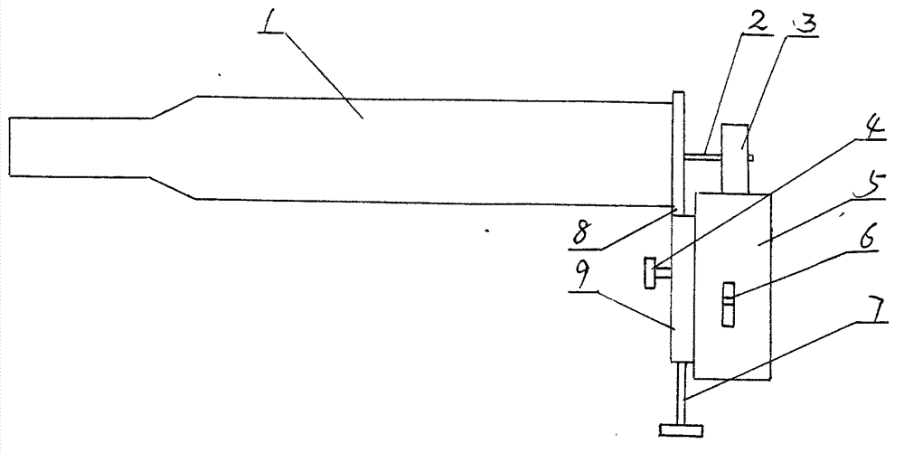
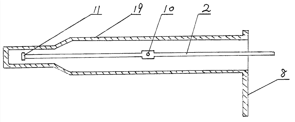
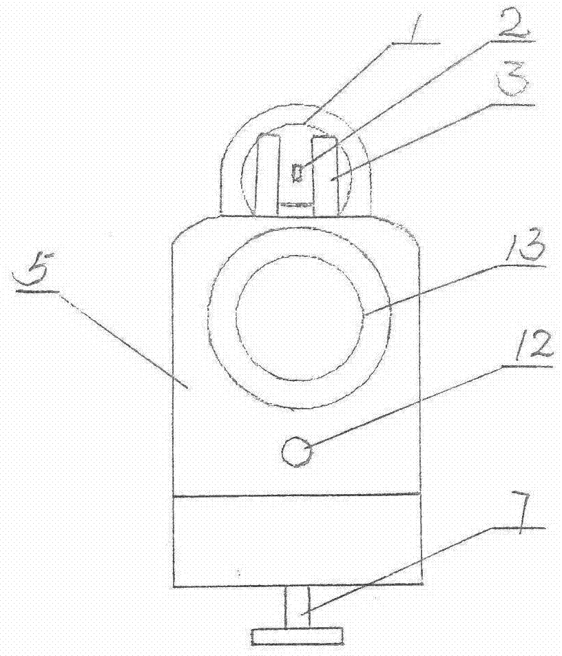
[0014] exist Figure 1-4 In the shown embodiment, the present invention comprises a magnetic sight 1, and this magnetic sight 1 has a cylindrical positioning tube 19 made of non-magnetic material, the front end of the positioning tube is closed and the rear end is open, and the hinge shaft 10 passes through the positioning tube. A swingable aiming indicator needle 2 is installed, and a magnet 11 is installed on the front end of the aiming indicator needle 2, and the magnet attracts the magnet 18 at the front end of the probe 17 inserted in the intramedullary nail 16. An electronic monitor 5 is installed at the positioning tube 19 rear end of the magnetic sight, and the housing upper end of the electronic monitor 5 is equipped with a fork seat 3 with a gap (that is, being made of two parallel poles) in the middle. Correspondingly installed on the two poles of the fork base 3 is a photoswitch that controls the electronic monitor 5 to prompt the alarm, and the rear end of the aim...


PUM


Abstract

The invention discloses a remote-end nail hole aiming monitor for an interlocking intramedullary nail, and belongs to the technical field of the medical equipment in the orthopedics department. The remote-end nail hole aiming monitor for the interlocking intramedullary nail comprises a magnetic aiming device, wherein the inside of the positioning tube of the magnetic aiming device is provided with an aiming pointer by a hinge; the front end of the aiming pointer is provided with a magnet; the rear end of the magnetic aiming device is provided with an electronic monitor unit; the upper end of the shell of the electronic monitor unit is provided with a forked standard of which the middle is provided with a notch; the inside of the forked standard is provided with a photoswitch used for controlling the electronic monitor unit to give an alarm; and the rear end of the aiming pointer extends into the notch of the forked standard. According to the remote-end nail hole aiming monitor for the interlocking intramedullary nail, which is disclosed by the invention, a sound-light alarm prompt can be carried out after aiming and positioning, and the aiming monitor is more convenient to operate. In addition, the whole hole drilling process can be monitored in real time, and a drill bit is prevented from deviating from the nail hole position so as to shorten the surgery time and lighten the pain of a patient.

Description

technical field [0001] The invention relates to the technical field of medical instruments for clinical osteosynthesis, in particular to a tool for assisting the installation of the distal locking nail of the intramedullary nail when the intramedullary nail is implanted in orthopedic surgery. Background technique [0002] At present, in the treatment of patients with tubular fractures, interlocking intramedullary nail internal fixation technology is widely used clinically, and the installation of the distal locking nail of the intramedullary nail is the key link of this technology. The position of the distal nail hole of the intramedullary nail The accuracy of positioning directly affects the difficulty and quality of surgery. There are several ways to target and locate the distal nail hole of the intramedullary nail that are commonly used in clinical practice. A large amount of radiation is produced, causing harm to medical staff and patients. The 2nd, adopt the position-...

Claims


Application Information

Patent Timeline
Patent Type & Authority Patents(China)
IPC IPC(8): A61B17/17A61B17/88
Inventor 李晓林孙德修
Owner SHANDONG HANGWEI ORTHOPEDICS MEDICAL INSTR
Why Eureka
Try Eureka