Wheel swing deburring device

A technology for deburring and wheel removal, applied in grinding machines, metal processing equipment, grinding/polishing equipment, etc., can solve problems such as low efficiency, single brush movement track, and poor burr treatment effect

Active Publication Date: 2013-05-01
CITIC DICASTAL
View PDF8 Cites 13 Cited by
  • Summary
  • Abstract
  • Description
  • Claims
  • Application Information

AI Technical Summary

Problems solved by technology

The traditional deburring method is to use a large disc brush to directly brush the back cavity, but this method has the following series of problems: The brush rotates at a certain angular velocity, and the linear velocity at different radii is different. The linear velocity at the outermost edge is higher, and the closer to the center, the lower the linear velocity, which makes the burr treatment effect at the corner near the flange not good.
Single brush movement trajectory
For long and narrow wheels with complex shapes, many windows, and a certain brushing time, a single brush movement track cannot effectively deal with the burrs of complex shapes, many windows, long and narrow wheels
Due to the existence of these problems, manual grinding is often required after the deburring machine has brushed the burrs. This is not only inefficient, but also the dust generated by grinding is very harmful to the human body.

Method used


Image

  • Wheel swing deburring device
  • Wheel swing deburring device
  • Wheel swing deburring device

Examples


Embodiment Construction

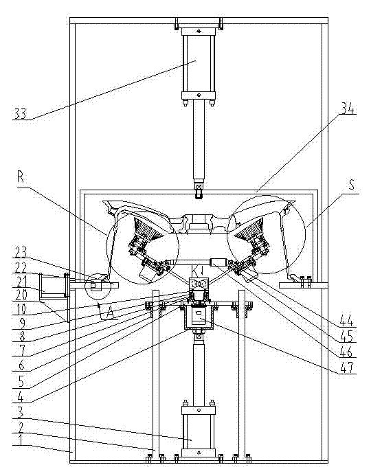
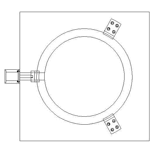
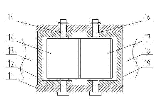
[0020] The details and working conditions of the specific device proposed according to the present invention will be described below in conjunction with the accompanying drawings.

[0021] A wheel swing deburring device, comprising a frame 1, a guide rod 2, and a lifting cylinder 3. Ear support 4, supporting plate 5, guide sleeve 6, bearing seat 7. Spacer sleeve 8. Bearing 9. Axis of rotation 10. Pendulum fixed seat 11. Gear seat 12. Pendulum 13. gear 14. Pin shaft 15. Pin shaft 16. gear 17. Pendulum 18. Gear seat 19. Side support plate 20, clamping cylinder 21, profiling claw 22, middle plate 23, motor 24. Big pulley 25. Block 26. Small pulley 27. Bearing seat 28. Bearing 29. Gland 30. Shaft 31. Brush 32. Lifting cylinder 33, dust cover 34, brush 35. Shaft 36. Gland 37. Bearing 38. Bearing seat 39. Small pulley 40. Block 41. Big pulley 42. Motor 43. Pin shaft 44, ear socket 45, servo electric rod 46 and motor 47. ...


PUM


Abstract

The invention discloses a wheel swing deburring device. The device consists of a rack, a motor, swing rod mechanisms, a lift mechanism, a swing rod rotary mechanism, an electric servo rod, gears, brushes, a clamp system and the like; the lift mechanism fixedly arranged on the rack is used for lifting the overall device, and applying certain pressure of the brushes to a spoke; the electric servo rod and two gears are used for adjusting the positions of two swing rod mechanisms at any time, so that the brush and the spoke part of a hub can be located in a best relatively parallel state; and while the brushes on the two swing rod mechanisms automatically rotate, the swing rod rotary mechanisms drive the brushes to perform revolution along the circumferential direction of a back cavity of the hub. The wheel swing deburring device provided by the invention can be used for uniformly removing contacted burrs of various hubs at various windows, parts and directions, all edges can be uniformly passivated effectively, and the deburring device is particularly suitable for a spoke with a hub with certain inclination.

Description

technical field [0001] The invention relates to a surface treatment device, in particular to a deburring device. Background technique [0002] In the production process of automobile wheels, it is a very important process to effectively remove the back cavity and corner burrs produced after machining, and the removal effect will directly affect the subsequent surface treatment effect. The traditional deburring method is to use a large disc brush to directly brush the back cavity, but this method has the following series of problems: The brush rotates at a certain angular velocity, and the linear velocity at different radii is different. The linear velocity at the outermost edge is higher, and the closer to the center, the lower the linear velocity, which makes the burr treatment effect at the corner near the flange not good. . In order to prevent the brush substrate from touching the wheel flange, the bristles of the brush must be made very long, so that the burrs are no...

Claims


Application Information

Patent Timeline
IPC IPC(8): B24B9/00
Inventor 薛博文郭建东刘伟东刘鸣华李文东
Owner CITIC DICASTAL
Why Eureka
Try Eureka